
Evaporation source and evaporation coating device

A technology of evaporation source and source material, which is applied in the field of film coater, can solve the problem of low utilization rate of source material, and achieve the effect of multi-region temperature control, simple and compact composition structure, and high melting point

Active Publication Date: 2013-08-21
ZHEJIANG SHANGFANG ELECTRONICS EQUIP
View PDF8 Cites 0 Cited by
  • Summary
  • Abstract
  • Description
  • Claims
  • Application Information

AI Technical Summary

Problems solved by technology

[0007] In order to improve the uneven temperature change in the evaporation container and improve the uniformity of film deposition, Mitsubishi Heavy Industries Co., Ltd. discloses a vacuum vapor deposition equipment in Chinese patent CN101942639 (2011-1-12), in which the evaporation container has a linearly arranged Multiple discharge holes with the same diameter, and a jet plate with multiple through holes with the same diameter, however, this method is mainly used to deposit a variety of evaporation materials, and the utilization rate of source materials is not high

Method used


Image

  • Evaporation source and evaporation coating device
  • Evaporation source and evaporation coating device
  • Evaporation source and evaporation coating device

Examples


Embodiment 1

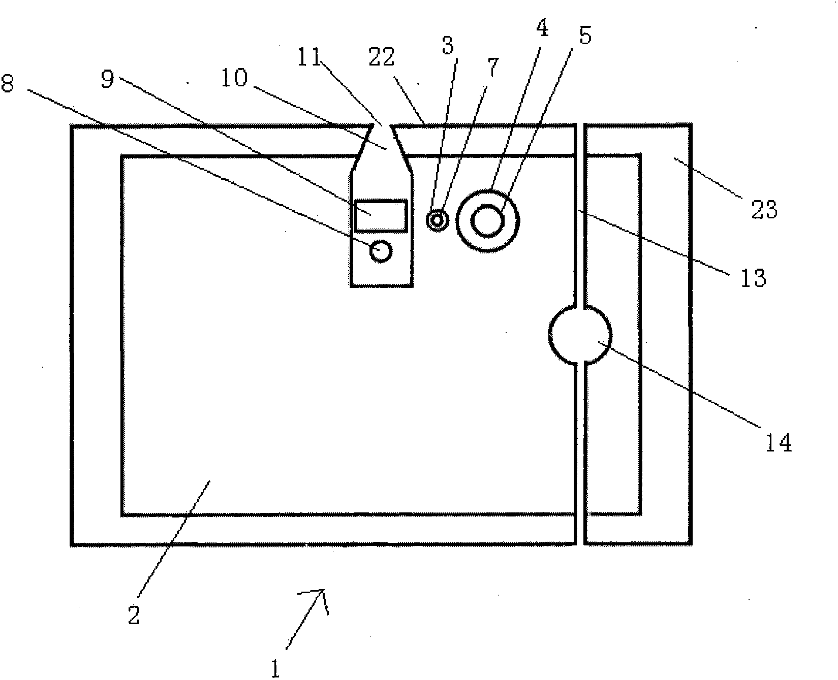
[0055] Such as figure 1 As shown, the evaporation source 1 is an integrated structure, including a temperature control module (see image 3 ), carrier gas inlet module (see Figure 4 and Figure 5 ), a feeding module, an exhaust module and a thermal insulation module 23, the five modules are all located in one evaporation source body 2, and the evaporation source body 2 is an integral structure formed by casting or cutting. The material of the evaporation source body is silicon carbide ceramics with a melting temperature of 2700°C and a thermal conductivity of 360w / mk. The material with high temperature resistance and good thermal conductivity is selected as the material of the evaporation source body 2, and the functional modules that make up the coating equipment are integrated into a single structure, that is, the evaporation source body 2, so that stable and uniform temperature control can be achieved, and the composition Evaporation source 1 with simple and compact str...

Embodiment 2

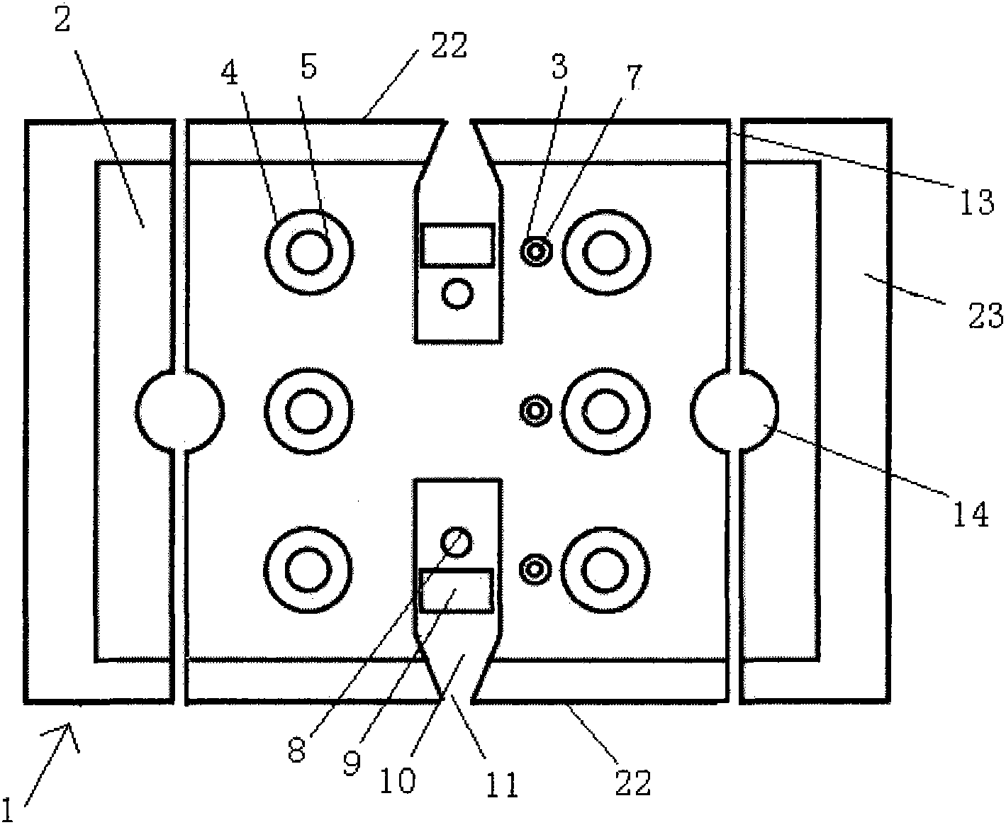
[0062] For the structure of evaporation source 1, see figure 2 , the difference from Embodiment 1 is that the evaporation source 1 has two opposite evaporation source working surfaces 22, and the temperature control module includes three pairs of ultraviolet heaters 5 and three thermocouples 7, the ultraviolet heater 5 and the thermocouple 7 A temperature controller 6 is connected between them, and three temperature controllers 6 are located outside the evaporation source body 2; the carrier gas inlet module includes two carrier gas distribution pipes 8 and two carrier gas inlets 17; the feeding module includes two source material chambers 9 and two injection ports 11; the exhaust module includes two waste gas outlets 13 and two exhaust pipes 14.

[0063] The material of the evaporation source body 2 is graphite ceramics with a melting temperature of 3500°C and a thermal conductivity of 150w / mk.

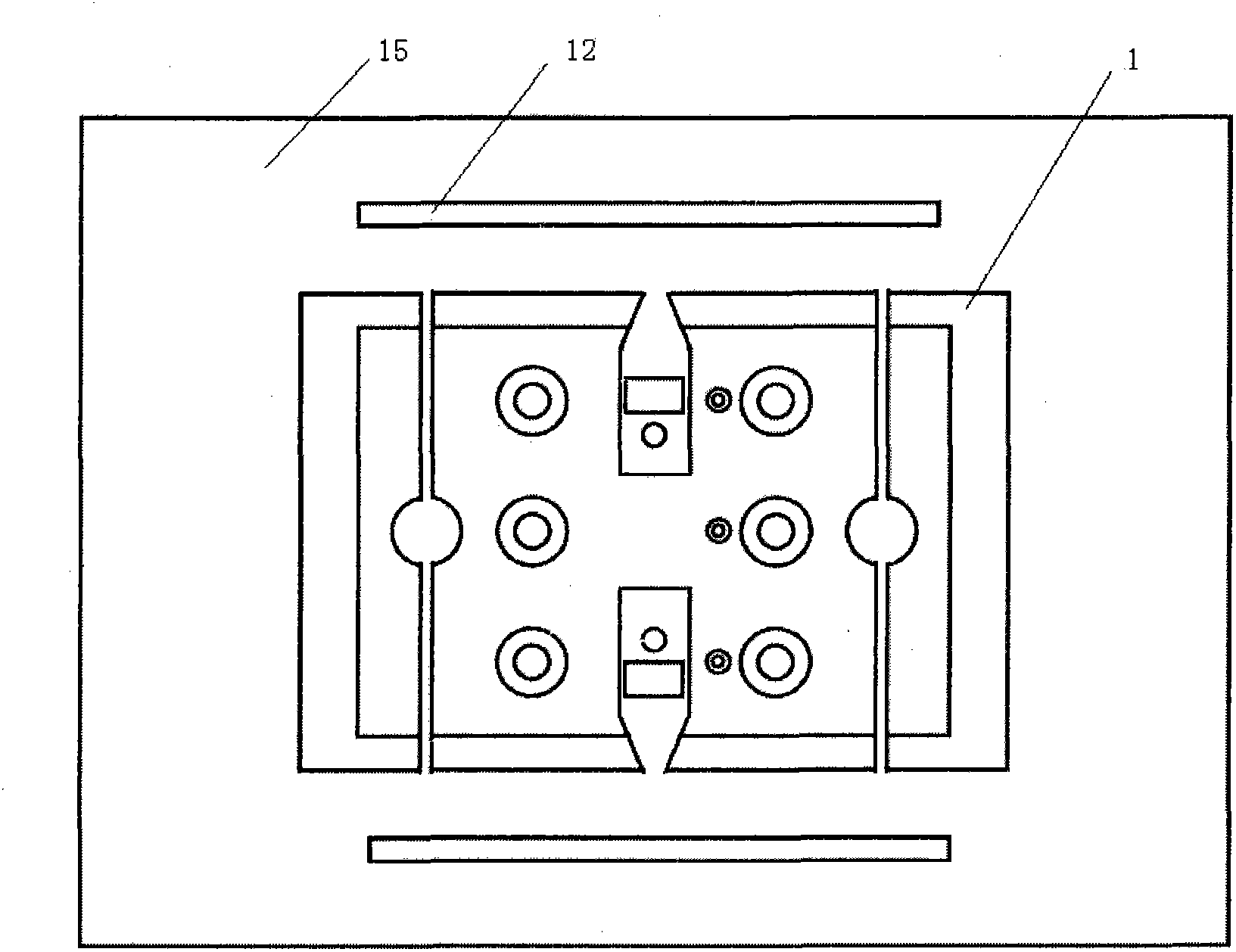
[0064] Such as image 3 As shown, the evaporation coating device 16 includes ...

Embodiment 3

[0067] The structure of the evaporation source 1 is the same as that of the second embodiment, except that there is no buffer chamber 10 between the source material chamber 9 and the source material steam injection port 11, the material of the evaporation source body is stainless steel, the melting temperature is 1400°C, and the thermal conductivity is 70w / mk. The material of the carrier gas distribution pipe 8 is silicon carbide with a melting temperature of 2700°C and a thermal conductivity of 360w / mk. The evaporation source body 2 has a spherical structure, and the heat insulation module 23 is composed of four arc-shaped heat insulation plates, surrounding the outer surface of the evaporation source body 2 .


PUM

PropertyMeasurementUnit
melting pointaaaaaaaaaa
pore sizeaaaaaaaaaa
melting pointaaaaaaaaaa

Abstract

The invention relates to a coating device applied to the field of semiconductors, LEDs and solar cells, in particular to an evaporation source and an evaporation coating device. The evaporation source comprises a temperature control module, a carrier gas inlet module, a feeding module, an exhaust module and a thermal insulating module, wherein the temperature control module, the carrier gas inletmodule, the feeding module and the exhaust module are all arranged in the evaporation source body, and the thermal insulating module encloses the external surface of the evaporation source body. The evaporation coating device comprises the evaporation source and a vacuum cavity surrounding the evaporation source. In this invention, various functional modules that constitute coating equipments areintegrated in a single structure, that is, the evaporation source body, so that the temperature can be controlled stably and uniformly, and the evaporation source and the evaporation coating device achieve simple and compact structure, high integral heat conductivity, high melting point, stable temperature, high raw material utilization rate and uniform coating.

Description

technical field [0001] The invention relates to a film coater used in the fields of semiconductors, LEDs and solar cells, in particular to an evaporation source and an evaporation coating device thereof. Background technique [0002] PECVD (Plasma Enhanced Chemical Vapor Deposition), PVD (Sputter Deposition), VTD (Vapor Transport Deposition) and CSS (Closed Space Sublimation, Heated Evaporation Coating) are thin film coating technologies widely used in semiconductor, LED, solar and other industries. [0003] Among them, the coating speed of PECVD and PVD is relatively slow. For thicker films, the production efficiency is not high, and the utilization rate of source materials is low. [0004] The VTD technology that has been widely used in recent years can only coat a single substrate. Due to structural limitations, the uniformity of the film is not good enough and the size of the substrate is limited. The conventional CSS technology cannot carry out continuous coating while...

Claims


Application Information

Patent Timeline
Patent Type & Authority Patents(China)
IPC IPC(8): C23C14/24
Inventor 赵军梅芳陈金良苏永顺
Owner ZHEJIANG SHANGFANG ELECTRONICS EQUIP
Learn More