
Surface-coated cutting tool

A cutting tool and surface coating technology, which is applied in the field of surface coating cutting tools, can solve the problems of low surface hardness and quick disappearance of the coating, and achieve the effects of excellent wear resistance, excellent heat resistance, and excellent lubricity

Active Publication Date: 2012-01-11
SUMITOMO ELECTRIC HARDMETAL CORP
View PDF9 Cites 2 Cited by
  • Summary
  • Abstract
  • Description
  • Claims
  • Application Information

AI Technical Summary

Problems solved by technology

[0015] However, none of the techniques in Patent Document 4 and Patent Document 5 can solve the problem of low surface hardness of the coating, and the outermost surface of the coating is prone to disappear quickly due to abrasion.

Method used


Image

  • Surface-coated cutting tool
  • Surface-coated cutting tool
  • Surface-coated cutting tool

Examples


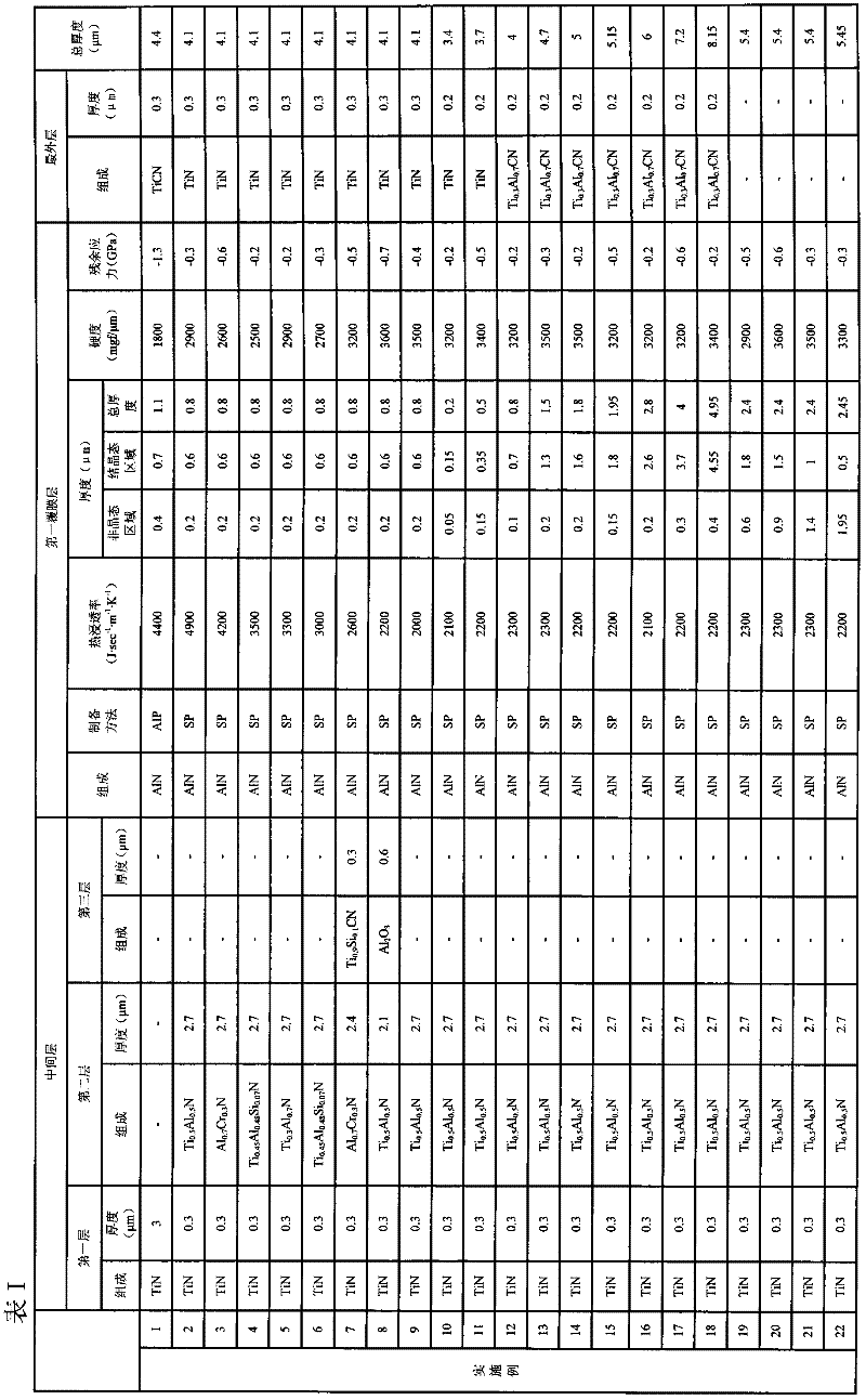
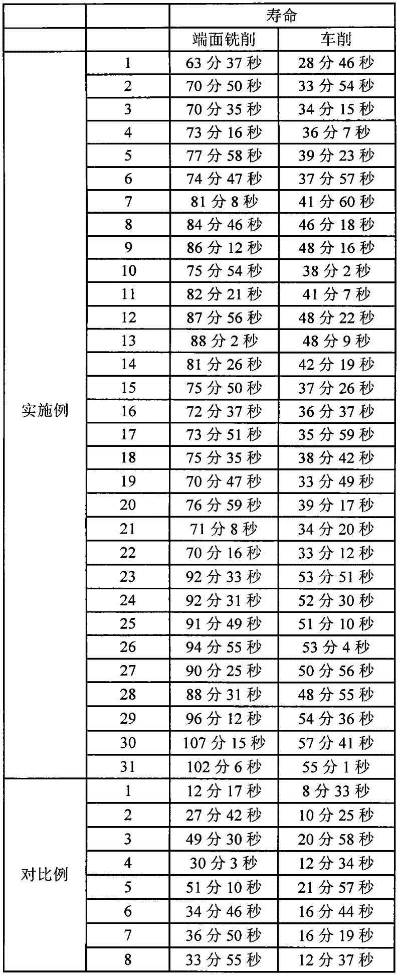
Embodiment 1 to 31 and comparative example 1 to 8

[0084] Surface-coated cutting tools were produced and evaluated as follows.

[0085]

[0086] First, as the base material of the surface-coated cutting tool, an indexable insert for face milling formed of P20 sintered carbide in the shape of SEET13T3AGSN (JIS) and an indexable insert formed of P20 sintered carbide in the shape of CNMG120408 (JIS) were produced. Indexable inserts for turning. These substrates were mounted on cathodic arc ion plating / sputtering equipment or CVD equipment.

[0087] Afterwards, the pressure in the chamber of the above device was reduced by a vacuum pump, and at the same time, the temperature of the substrate was raised to 600 °C by a heater installed in the device, and the chamber was evacuated until the internal pressure dropped to 1.0×10 -4 Pa.

[0088] Next, the tungsten filament was heated by gradually raising the voltage of the substrate bias power supply of the substrate to -1,500 V so that argon gas was introduced into the chamber while...


PUM

PropertyMeasurementUnit
deposition rateaaaaaaaaaa

Abstract

Disclosed is a surface-coated cutting tool in which the adhesion of a coating upon a base is high and which combines excellent heat resistance, excellent abrasion resistance, and excellent lubricity. The surface-coated cutting tool is provided with a substrate and a coating that has been formed upon said substrate, and is characterized in that: said coating is formed by means of the physical vapor deposition method and comprises one or more layers; at least one layer from among said one or more layers is a first coating layer; said first coating layer comprises Al and N, and has a thermal effusivity in the range of 2000 J / sec-1 m-1 K-1 to 5000 J / sec-1 m-1 K-1 and a coating thickness in the range of 0.2 [mu]m to 5 [mu]m; the first coating layer has an amorphous region and a crystalline region from the substrate side in this order; the amorphous region comprises an amorphous material and has a thickness in the range of 0.01 [mu]m to 2 [mu]m; and the crystalline region comprises a crystal structure that includes a hexagonal structure.

Description

technical field [0001] The present invention relates to a surface-coated cutting tool having a substrate and a coating formed on the substrate. Background technique [0002] As a recent trend of cutting tools, the temperature of the cutting edge of the tool tends to become higher and higher due to the following reasons: dry machining without using cutting lubricants is required from the viewpoint of global environmental protection, workpiece Diversification and increased cutting speed to further improve machining efficiency. Therefore, the required characteristics of tool materials become more stringent. In particular, as the characteristics required of tool materials, not only heat resistance of the coating formed on the base material is a matter of course, but also the improvement of wear resistance related to the life of the cutting tool and the lubrication of the coating instead of lubricant Performance has also become increasingly important. [0003] In order to impr...

Claims


Application Information

Patent Timeline
Patent Type & Authority Applications(China)
IPC IPC(8): B23B27/14B23B51/00B23C5/16C23C14/06
CPCC23C28/048C23C14/06C23C28/044C23C30/005C23C28/046C23C14/0641Y10T428/24975Y10T428/265Y02T50/60B23B27/14B23B51/00B23C5/06C22C27/04C23C28/021
Inventor 小池沙知子今村晋也山县一夫
Owner SUMITOMO ELECTRIC HARDMETAL CORP
Learn More