


Quick Research
Generate reliable direction feasibility study reports for your R&D in just a few steps.

Technical Q&A
Discover and master advanced knowledge NOW. Basics, ideas, possibilities, all at once.

Find Solutions
As an expert in R&D theories, this can generate solutions to your technical problems instantly.

Evaluate Feasibility
Analyze your overall solution with one click, know your potential R&D risks in advance.

Monitor Landscape
Get weekly tech updates, stay abreast of the latest tech innovations and key insights.
Oxide field effect transistor
A technology of field effect transistors and amorphous oxides, applied in the field of field effect transistors, can solve problems such as limitations and achieve the effect of excellent environmental stability
- Summary
- Abstract
- Description
- Claims
- Application Information
AI Technical Summary
Problems solved by technology
Method used
Image

Examples
example 1
[0092] In this example, the top-gate TFT device shown in FIG. 8 was fabricated using an In-Mg-O-based amorphous oxide as a channel layer.
[0093] First, an In-Mg-O-based amorphous oxide film was formed as a channel layer on a glass substrate (1737 manufactured by Corning Incorporated). use Figure 10 This film was formed by high-frequency sputtering in a mixed atmosphere of argon and oxygen in the apparatus shown in . exist Figure 10 In , samples, targets, vacuum pumps, vacuum gauges, and substrate holders are denoted by reference numerals 51, 52, 53, 54, and 55, respectively. A gas flow rate controller 56 is provided for each gas introduction system. The pressure controller and the film forming chamber are denoted by reference numerals 57 and 58, respectively. The vacuum pump 53 is an exhaust unit for evacuating the inside of the film forming chamber 58 . The substrate holder 55 is a unit within the film formation chamber for holding a substrate on which an oxide film ...
example 2
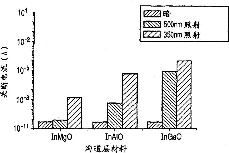
[0113] In this example, In-Mg composition dependence was examined in a thin film transistor having a channel layer containing In and Mg as main components.
[0114] In order to examine the material composition dependence of the channel layer, this example employs a combined method of TFT fabrication (channel layer formation). In other words, a TFT compositional library was constructed using a method of forming a composition-changed oxide film on a single substrate by sputtering. However, such a combination method is not necessary, and a target of a given composition may be prepared to form a film, or a thin film of a desired composition may be formed by separately controlling input power for a plurality of targets.
[0115] The In-Mg-O film was formed using a triple grazing incidence sputtering device. Where the target is positioned at an angle relative to the substrate, the composition of the film on the substrate surface changes due to the difference in distance from the ta...
example 3
[0132] In this example, the channel layer was formed of In-Al-O-based amorphous oxide, and a device using this channel layer was fabricated and evaluated by the same method as that employed in Example 1. Figure 8A A top-gate TFT device is shown.
[0133] In the size of 2 inches2 o 3 and Al 2 o 3 A target (purity: 99.9%) was used to form an In—Al—O film by simultaneous sputtering. The input RF power was 60W and 180W for the previous and subsequent targets. Set the atmosphere for film formation so that the total pressure is 0.4 Pa and the gas flow rate ratio is Ar:O 2 =150:1. The film formation rate and substrate temperature were set to 11 nm / min and 25°C, respectively. Subsequently, the film was annealed at 280° C. for 30 minutes in the atmosphere.
[0134] Irradiation angle X-ray diffraction (thin film method, incident angle: 0.5°) was performed on the surface of the obtained film. No obvious diffraction peaks were detected, which indicated that the formed In-Al-O bas...
PUM
 Abstract
Description
Claims
Application Information
 - R&D Engineer
- R&D Manager
- IP Professional
- Industry Leading Data Capabilities
- Powerful AI technology
- Patent DNA Extraction
Browse by: Latest US Patents, China's latest patents, Technical Efficacy Thesaurus, Application Domain, Technology Topic, Popular Technical Reports.
© 2024 PatSnap. All rights reserved.Legal|Privacy policy|Modern Slavery Act Transparency Statement|Sitemap|About US| Contact US: help@patsnap.com