

Industrial smoke exhaust gas recovery purifier and application method thereof
A technology of waste gas recovery and purification device, applied in the field of environmental engineering, can solve the problems of poor treatment effect, small adsorption force of waste gas, and high treatment cost, and achieve the effects of reducing pollution sources, increasing reaction speed, and increasing reaction area
- Summary
- Abstract
- Description
- Claims
- Application Information
AI Technical Summary
Problems solved by technology
Method used
Image

Examples
Embodiment Construction
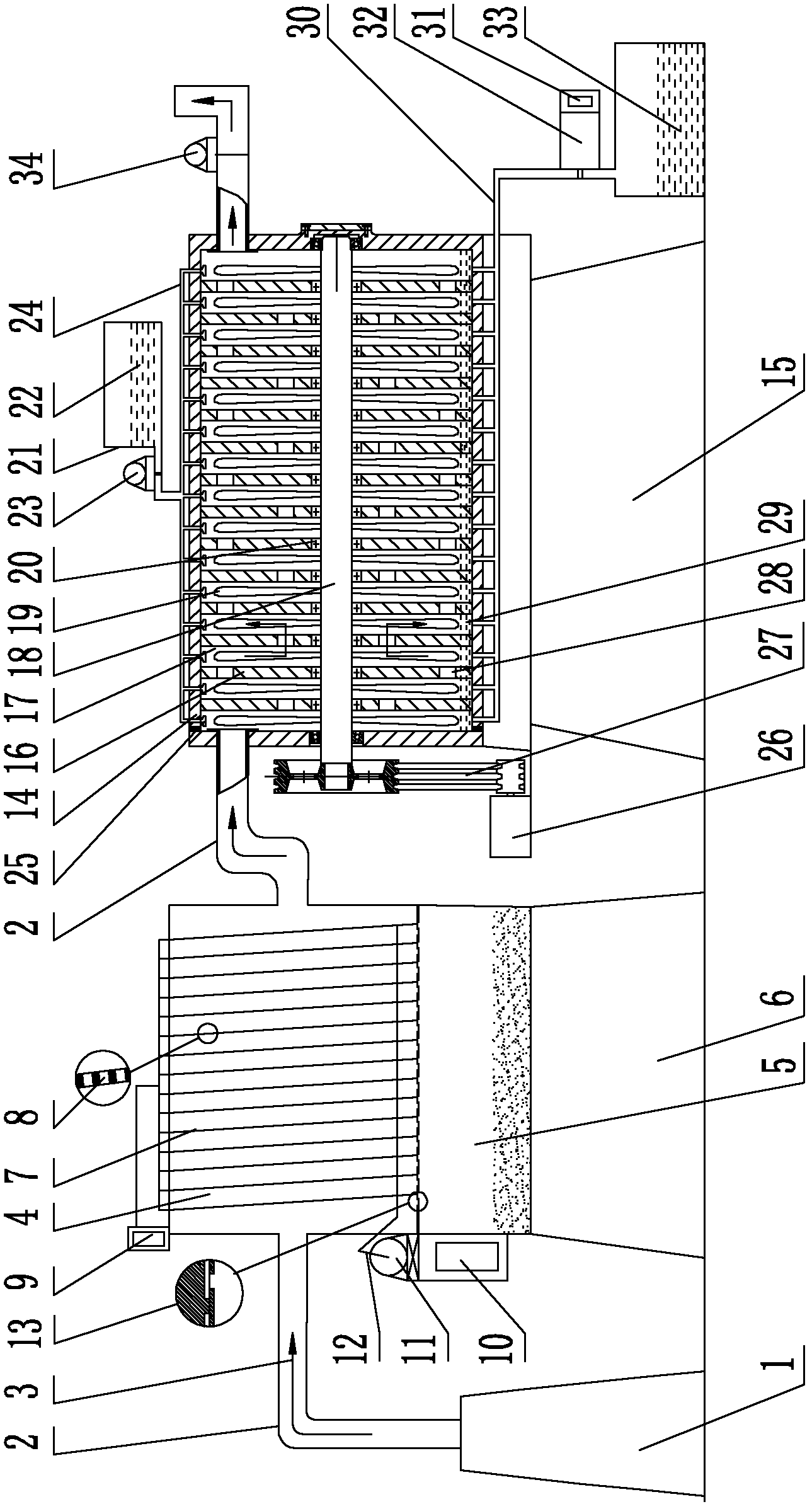
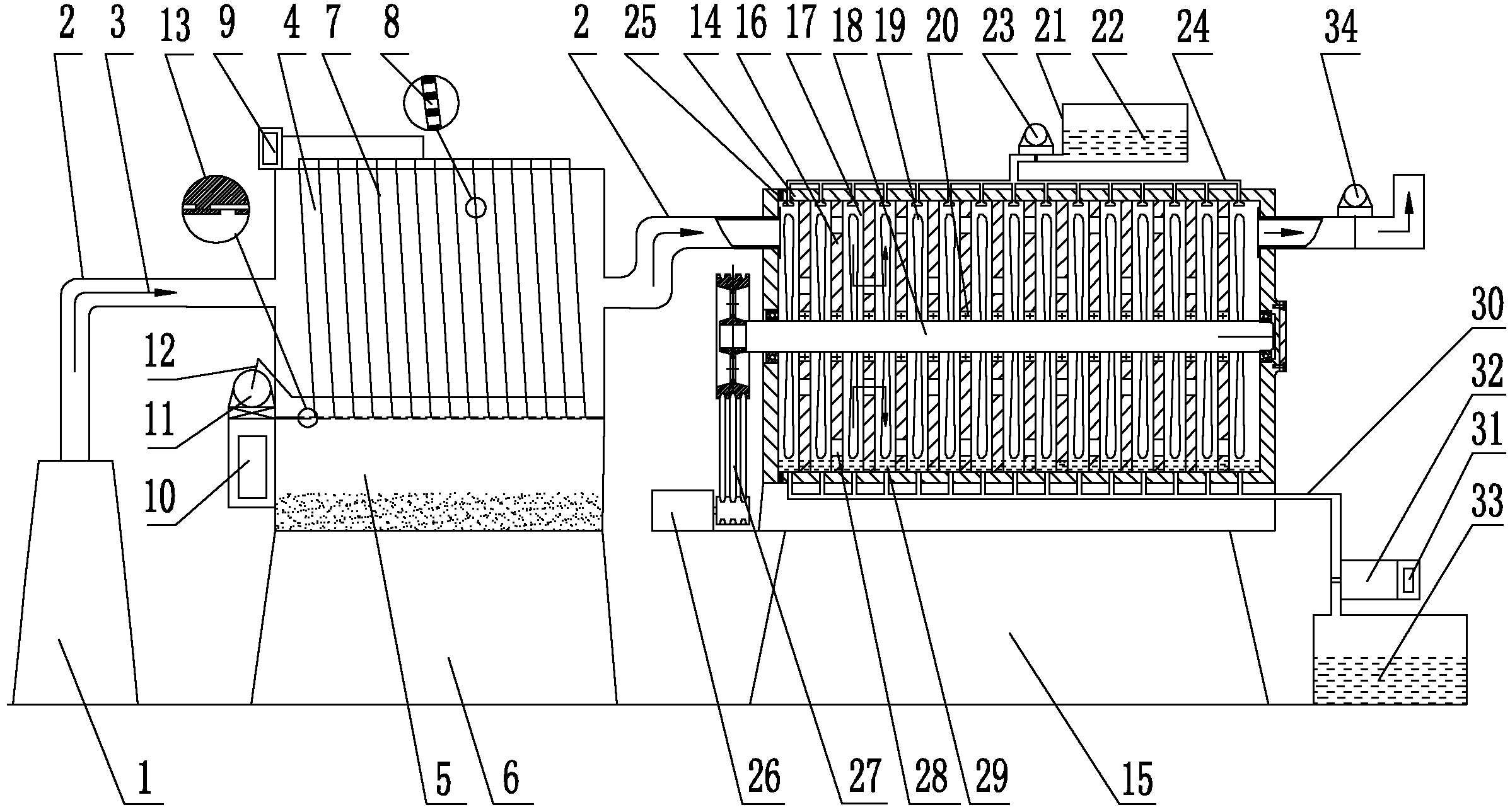
[0024] Now provide following embodiment and further describe the present invention in conjunction with accompanying drawing:
[0025] The exhaust pipe (2) is respectively connected to the chimney (1) and the dust removal chamber (4), and the bottom of the dust removal chamber (4) is connected to the dust box (5), and the dust box (5) is fixed on the dust removal room support (6), and the dust removal chamber ( 4) There are 15 inclined grid plates (7) inside, each grid plate (7) has a grid hole (8), and the grid holes (8) on the adjacent grid plate (7) The size is different, gradually decreasing from front to back, the grid plate (7) is connected with the grid plate controller (9) located on the upper part of the dust removal chamber (4), and the bottom of the dust removal chamber (4) is provided with a dust discharge port (13), A dust removal room controller (10) is arranged outside the dust box (5), a dust removal motor (11) is arranged outside the dust removal room (4), and ...
PUM
 Abstract
Description
Claims
Application Information