Preparation method of hydrogen storage material nano catalysis system

A hydrogen storage material and nano-catalysis technology, applied in the field of hydrogen storage materials, can solve the problems of low dispersion distribution, pollution of hydrogen sources, and difficulty in obtaining catalytic phase composite structure, so as to optimize structure and performance, ensure uniform phase composite, and broad The effect of applying the foreground

Inactive Publication Date: 2012-05-23
INST OF METAL RESEARCH - CHINESE ACAD OF SCI
View PDF3 Cites 5 Cited by
  • Summary
  • Abstract
  • Description
  • Claims
  • Application Information

AI Technical Summary

Problems solved by technology

When the inorganic compound precursor is used, the added phase reacts with the matrix material to form an inert impurity phase, resulting in a decrease in the actual hydrogen storage capacity of the system; when the wet chemical method or organic compound precursor is used, a composite hydrogen storage with uniform distribution of nano-clusters can be prepared materials, but at the same time, a considerable amount of organic ligands will be introduced into the system, causing hydrocarbons to pollute the hydrogen source during the heating process of the system; although the direct use of transition metal powder and hydrogen storage material mixed ball milling can solve the above problems, but it is limited Due to the limitations of the ball milling technology, it is difficult to obtain the ideal composite structure of the catalytic phase (large particles of the catalytic phase and low degree of dispersion distribution), resulting in poor kinetic performance of the material for hydrogen storage and release.

Method used


Image

  • Preparation method of hydrogen storage material nano catalysis system
  • Preparation method of hydrogen storage material nano catalysis system
  • Preparation method of hydrogen storage material nano catalysis system

Examples


Embodiment 1

[0042] Adopt NaH / Al powder mixture as starting material, apply the method and device of the present invention to prepare Ti-NaAlH 4 Composite catalytic system and post-milling treatment.

[0043] The raw materials used are: NaH (purity 95wt%, ~100 mesh), Al (purity 99.9wt%, ~325 mesh), high-purity Ti target (purity>99.99wt%).

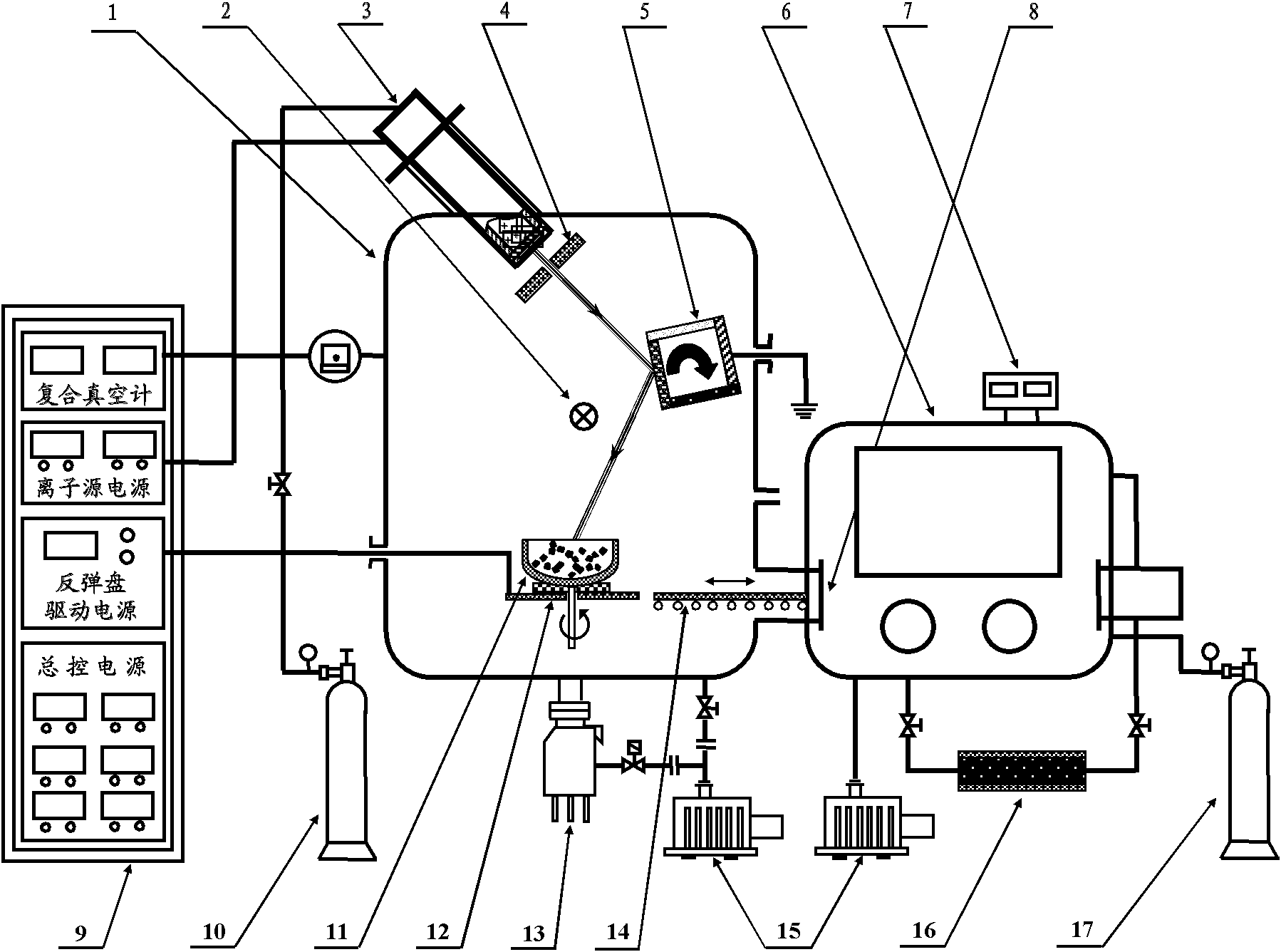
[0044] Sample preparation process: in an argon atmosphere glove box, a NaH / Al powder mixture (molar ratio of 1:1) sample (about 0.5 g) was placed in a rebound pan, and the valve between the glove box and the vacuum chamber was opened. Seal the hatch, transfer the rebound disk to the vacuum chamber through the sample transfer mechanism and fix it to the rebound disk drive device. After closing the airtight hatch, turn on the mechanical pump and the molecular pump in sequence to evacuate the vacuum chamber to 5×10 -4 Pa, fill the vacuum chamber with high-purity argon (volume purity ≥99.9999%) to about 5×10 -2 Pa, then turn on the sputter ion source. A...

Embodiment 2

[0050] The difference from Example 1 is that using NaAlH 4 As a raw material, the method and device of the present invention are used to prepare Ti-NaAlH 4 Composite catalytic system and post-milling treatment.

[0051] The raw material used is: NaAlH 4 (purity 90wt%, ~100 mesh), high-purity Ti target (purity>99.99wt%).

[0052]The sample preparation process is the same as in Example 1. During the ion sputtering process, the discharge voltage was set to 80V, the filament current was 6A, the accelerating voltage was 200V, the beam current voltage was 900V, and the filament current was adjusted to a beam current of 20mA. The sputtering time was 0.5 hours. The post-milling treatment was carried out under the atmosphere of high-purity Ar (volume purity 99.999%), the mass ratio of ball to material was 40:1, and the ball milling time was 2 hours. In this example Ti-NaAlH 4 In the composite material, the molar percentage of Ti is about 0.5%, and the rest is NaAlH 4 .

[0053]...

Embodiment 3

[0055] The difference from Example 1 is that the method and device of the present invention are used to prepare Fe-NaAlH 4 Composite catalytic system and post-milling treatment.

[0056] The raw material used is: NaAlH 4 (purity 90wt%, ~100 mesh), high-purity Fe target (purity>99.9wt%).

[0057] The sample preparation process is the same as in Example 1. During the ion sputtering process, set the discharge voltage to 70V, the filament current to 5A, the acceleration voltage to 180V, the beam current voltage to 800V, and adjust the filament current to a beam current of 18mA. The sputtering time was 0.5 hours. The post-milling treatment is carried out under the atmosphere of high-purity Ar (volume purity 99.999%), the mass ratio of ball to material is 40:1; the ball milling time is 5 hours. This embodiment Fe-NaAlH 4 In the composite material, the molar percentage of Fe is about 2%, and the rest is NaAlH 4 .

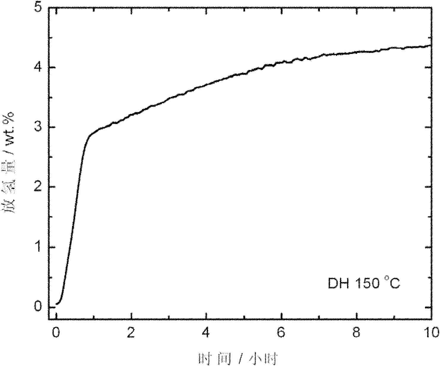
[0058] Figure 6 The prepared Fe-NaAlH 4 Hydrogen desorption...


PUM

PropertyMeasurementUnit
sizeaaaaaaaaaa
sizeaaaaaaaaaa

Abstract

The invention relates to the field of hydrogen storage materials, in particular to a preparation method of a hydrogen storage material nano catalysis system. A catalyst nano particle is prepared by combining and applying an ion beam sputtering or magnetic control sputtering technology and a rebounding disk technology, a transition metal nano particle is prepared by adopting an ion beam sputtering or magnetic control sputtering transition metal target material, hydrogen storage material powder is driven by adopting the rebounding disk technology to make a multiple-dimensional and/or multiple-mode movement, and in-situ uniform surface phase compounding of the catalyst nano particle and the hydrogen storage material powder is realized. A device for preparing the hydrogen storage material nano catalysis system comprises a sputtering system, a nano particle/powder material composite system and a feeding/sampling system. The invention is suitable for preparing various hydrogen storage material nano catalysis systems. The hydrogen storage material nano catalysis system prepared by adopting the invention has hydrogen storage performance remarkably superior to the material prepared by adopting the traditional metal phase ball grinding method.

Description

Technical field [0001] The invention relates to the field of hydrogen storage materials, in particular to a method for preparing a hydrogen storage material nano-catalysis system. Background technique [0002] Hydrogen energy is a clean and renewable energy, which provides an ideal energy source for human beings to fundamentally solve the problems of fossil energy shortage and environmental pollution. However, the realization of large-scale application of hydrogen energy faces many severe technical challenges, among which on-board hydrogen storage is the most challenging "bottleneck" link. In order to meet the commercialization needs of "hydrogen-fueled vehicles", the on-board hydrogen storage system must have high hydrogen storage density, mild operating temperature, high hydrogen absorption and desorption rate, long cycle life, high operational safety and moderate price and cost. Among the existing hydrogen storage methods, material-based solid-state hydrogen storage is f...

Claims


Application Information

Patent Timeline
Patent Type & Authority Applications(China)
IPC IPC(8): C01B3/06
CPCY02E60/362Y02E60/36
Inventor 王平康向东
Owner INST OF METAL RESEARCH - CHINESE ACAD OF SCI
Why Eureka
Try Eureka