Polymerization process using a supported constrained geometry catalyst
A polymerization method and geometry technology, which are applied in the field of polymerization using supported catalysts with restricted geometry, can solve the problems of reducing catalyst efficiency and catalyst productivity, etc.
- Summary
- Abstract
- Description
- Claims
- Application Information
AI Technical Summary
Problems solved by technology
Method used
Image
Examples
Embodiment 1
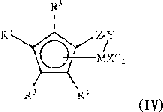
[0277] In the examples, supported metallocene catalysts based on constrained geometry metallocenes were prepared by the following steps as taught extensively in US Pat. No. 5,783,512 [(C 5 Me 4 SiMe 2 N t Bu)Ti(η 4 -1,3-pentadiene)], the catalyst is used together with a discrete borate ester activator.
[0278] To a 1 gallon mixing tank was added 0.92 kg of Davison 955 silica (commercially available from W. R. Grace & Co.-Conn., 7237 East Gage Ave., Los Angeles, CA 90040), which had been previously dehydrated at 200°C. 0.51 kg of dry hexane was added to the mixing tank, followed by 2.6 kg of 10 wt% triethylaluminum (TEAL) in hexane (-2.5 mmole TEAL / g silica). The slurry was mixed for approximately 2 hours, after which time the solid was filtered and washed with 4 1.6 kg portions of dry hexane. The resulting solid was dried overnight under nitrogen to yield 1.1 kg of TEAL-treated silica.
[0279] In a glove box under an inert gas atmosphere, dilute 303 mL of a 0.08 M solu...
Embodiment 2
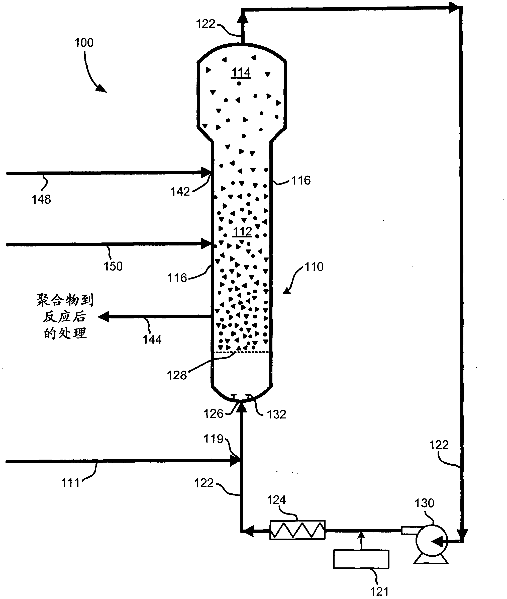
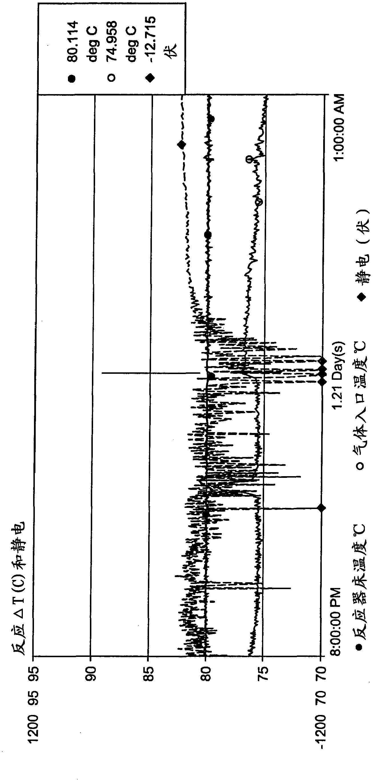
[0281] The tests were carried out in the aforementioned polymer reactor using the aforementioned sCGC catalyst without any continuity additives. The sCGC catalyst is used to produce a film product with a melt index of about 1.0-1.2 and a density of 0.918-0.919. The reaction conditions during the operation of the reactor are: reaction temperature 80°C, ethylene concentration 44.7% by mole, moles of hexane and ethylene The ratio was 0.0037, and the hydrogen concentration was 1096 ppm. Static levels measured by static probes placed in the bed showed an increase in activity accompanied by a spike at negative polarities above 1200 volts, where the polymer precursors adhered to the reactor and triggered events such as figure 2 Crust shown.
Embodiment 3
[0283] In this test, the reactor was run under conditions similar to those described in Example 2 above, except that a continuity additive was used. The aforementioned continuity additive (mixture of aluminum distearate and ethoxylated amine type compound (IRGASTAT AS-990)), also called CA-mixture feedstock and sCGC catalyst was used to start up the reactor. The concentration of the CA mixture fed to the reactor was 13.2 ppmw based on production rate. like figure 2 As shown in , within 2 hours of starting the addition of the CA mixture cofeed to the reactor, the static level narrowed and the negative spike in the static reading disappeared. The reactor ran smoothly and no skinning or aggregation occurred.
PUM
 Abstract
Description
Claims
Application Information
 - R&D
- Intellectual Property
- Life Sciences
- Materials
- Tech Scout
- Unparalleled Data Quality
- Higher Quality Content
- 60% Fewer Hallucinations
Browse by: Latest US Patents, China's latest patents, Technical Efficacy Thesaurus, Application Domain, Technology Topic, Popular Technical Reports.
© 2025 PatSnap. All rights reserved.Legal|Privacy policy|Modern Slavery Act Transparency Statement|Sitemap|About US| Contact US: help@patsnap.com


