Photon counting full-spectrum direct reading fluorescence spectrometer

A fluorescence spectrometer and photon counting technology, applied in the new field of fluorescence spectrometer, can solve the problems of high production and operation cost, complex structure, high sensitivity, etc., and achieve the effect of low production and operation cost, large linear dynamic range and good operation stability

Active Publication Date: 2012-06-20
广东世绘林科技有限公司
View PDF5 Cites 8 Cited by
  • Summary
  • Abstract
  • Description
  • Claims
  • Application Information

AI Technical Summary

Problems solved by technology

[0030] 1) Fluorescence spectrometers that use simple "charge integration method" for spectral analysis (such as detectors using CCD or CID or PD arrays, etc.), although the purpose of "full-spectrum direct reading" can be achieved, the corresponding "detection sensitivity " and "data stability" will be quite limited, "reading accuracy" and "linear dynamic range" will also be affected to a certain extent, and there is a serious signal overflow problem
[0031] 2) Fluorescence spectrometers that use a simple "photon counting method" to perform spectral analysis in a scanning manner (for example, the detector uses PMT or APD, etc.), although the corresponding "detection sensitivity" and "data stability" can be greatly improved, "Reading accuracy" and "linear dynamic range" can also be optimized to a certain extent, but "full-spectrum direct reading" cannot be achieved, and many advantages of "full-spectrum direct reading" cannot be achieved
Therefore, the advantages of the traditional atomic fluorescence spectrometer are mainly reflected in the sensitivity, that is, high sensitivity (low detection limit); if the "photon counting method" is adopted, it also has good data stability, high reading accuracy, large linear dynamic range and It has the advantages of not being affected by the signal overflow problem; the disadvantage is that it cannot be "full-spectrum direct reading", that is, it cannot analyze multiple material components at the same time, cannot make full use of every spectral line in the working wavelength range, slow working speed, complex structure, and difficult to operate. Poor stability (not suitable for on-site detection and online monitoring in harsh working conditions), relatively high production and operation costs, and cumbersome upgrades and adjustments, etc.

Method used


Image

  • Photon counting full-spectrum direct reading fluorescence spectrometer
  • Photon counting full-spectrum direct reading fluorescence spectrometer
  • Photon counting full-spectrum direct reading fluorescence spectrometer

Examples


Embodiment 1

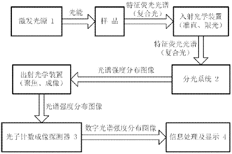
[0066] Such as figure 1 As shown, a photon counting full-spectrum direct-reading fluorescence spectrometer is mainly composed of an excitation light source 1, a spectroscopic system 2, a photon counting imaging detector 3, and information processing and display 4:

[0067] The excitation light source 1 is a light source device capable of providing light energy to excite the sample to generate a characteristic fluorescence spectrum;

[0068] Spectroscopic system 2 is a dispersion spectroscopic device capable of dispersing composite light into monochromatic light or spectral intensity distribution images;

[0069] The photon counting imaging detector 3 is an image sensor capable of position-sensitive detection and photon counting;

[0070] Information processing and display 4 is used to receive and process optical images, and express the processing and analysis results in various graphic forms that are easy for people or machines to understand;

[0071] The optical connections...

Embodiment 2

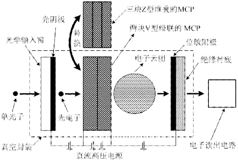
[0089]This embodiment is basically the same as Embodiment 1, the difference is that: on the basis of the photon counting imaging detector 3 described in Embodiment 1, a semiconductor layer can be added between the MCP output terminal and the position-sensitive anode, and the MCP There is a gap between the output terminal and the semiconductor layer, the semiconductor layer is plated on the insulating substrate, and the DC high-voltage power supply is electrically connected to the semiconductor layer through a high-voltage lead wire or a conductive electrode (such as Figure 4 shown). At this time, the above step S540, that is, the physical process of collecting the electron cloud by the position-sensitive anode, evolves into: the electron cloud first crosses to the semiconductor layer under the action of the accelerating bias electric field, and then is induced to the position-sensitive anode through charge induction.

Embodiment 3

[0091] This embodiment is basically the same as Embodiment 1, except that: on the basis of the fluorescence spectrometer described in Embodiment 1, the excitation light source 1 can use a variety of different types of light source devices, either a continuous light source or a continuous wavelength Or discretely tunable lasers, sharp-line light sources or fixed-wavelength lasers (preferably continuous light sources) can also be used, from which a variety of photon counting full-spectrum direct-reading fluorescence spectrometers based on different excitation light sources can be derived.

[0092] For example: a continuous light source can use a high-intensity short-arc xenon lamp. At this time, a variety of characteristic fluorescence spectra and multiple characteristic fluorescence spectral lines produced by various material components can be analyzed; a sharp-line light source can use a high-intensity hollow cathode lamp. At this time It can analyze multiple characteristic flu...


PUM


Abstract

The invention provides a photon counting full-spectrum direct reading fluorescence spectrometer, which is mainly composed of an excitation light source, a spectrometer system, a photon counting imaging detector and an information processing and displaying unit. The excitation light source provides light energy to excite a sample to generate a characteristic fluorescence spectrum; the spectrometer system subjects the incident composite light containing the characteristic absorption spectrum to dispersion to give a spectral intensity distribution image; the photon counting imaging detector reconstructs the spectral intensity distribution image in a digital manner through position sensitive detection and photon counting; and the information processing and displaying unit performs qualitative and quantitative analysis on the sample according to the light intensity and the position of each image element in the digital spectral intensity distribution image. The spectrometer of the invention combines advantages of photon counting technology and full-spectrum direct reading technology, is low in detection limit, high in reading precision, good in data stability and large in linear dynamic range, can simultaneously analyze multiple substance components and make full use of each spectral line in a working wavelength range, and is rapid in working speed, simple in structure and good in operation stability.

Description

technical field [0001] The invention relates to a brand-new fluorescence spectrometer, that is, a photon counting full-spectrum direct-reading fluorescence spectrometer based on a "photon counting imaging detector". [0002] The invention is especially suitable for trace or ultra-trace analysis of atoms (elements), molecules, ions and other material components, and can be widely used in environmental monitoring, food safety, bio-optics, metallurgy, chemical engineering, geological exploration, medicine and health, etc. Industry and subject technical fields. Background technique [0003] Fluorescence refers to the excitation of substances after absorbing light radiation, and the excited substances (atoms, molecules, ions or other substances) re-emit radiation with the same or different wavelengths as the excitation radiation during the de-excitation process. When the excitation light source stops irradiating the sample, the re-emission process stops immediately, and this re-...

Claims


Application Information

Patent Timeline
Patent Type & Authority Applications(China)
IPC IPC(8): G01N21/64G01J11/00
Inventor 缪震华文敏黄涛吕权息张庆赖胜波尹延静张利
Owner 广东世绘林科技有限公司
Why Eureka
Try Eureka