An electro-oxidative ozone generator

An ozone generator and electro-oxidation technology, applied in the direction of electrodes, electrolytic processes, electrolytic components, etc., can solve the problems of increased contact resistance, high energy consumption and temperature rise, long start-up time, etc., to achieve reduced resistance and energy consumption, high Ozone generation efficiency and the effect of simple equipment manufacturing

Active Publication Date: 2017-05-17
CHANGZHOU UNIV +1
View PDF13 Cites 3 Cited by
  • Summary
  • Abstract
  • Description
  • Claims
  • Application Information

AI Technical Summary

Problems solved by technology

However, in practical applications, the catalyst layer of the independent sheet structure needs to use (PTFE) and other binders, which increases the resistance of the catalyst layer itself and the contact resistance between the layers, resulting in high energy consumption and temperature rise; although in the form of electroplating A lead dioxide catalyst layer can be formed on the anode, but the resulting electrode layer is very uneven and easily broken, which causes the generator to have high resistance and a short service life; patent CN200610138715 is used on the surface and pores of porous titanium plates The ozone generator made by deposition catalyst method has the obvious disadvantages of long start-up time and high voltage in practical application due to the limitation of technology itself

Method used


Image

  • An electro-oxidative ozone generator
  • An electro-oxidative ozone generator
  • An electro-oxidative ozone generator

Examples


Embodiment 1

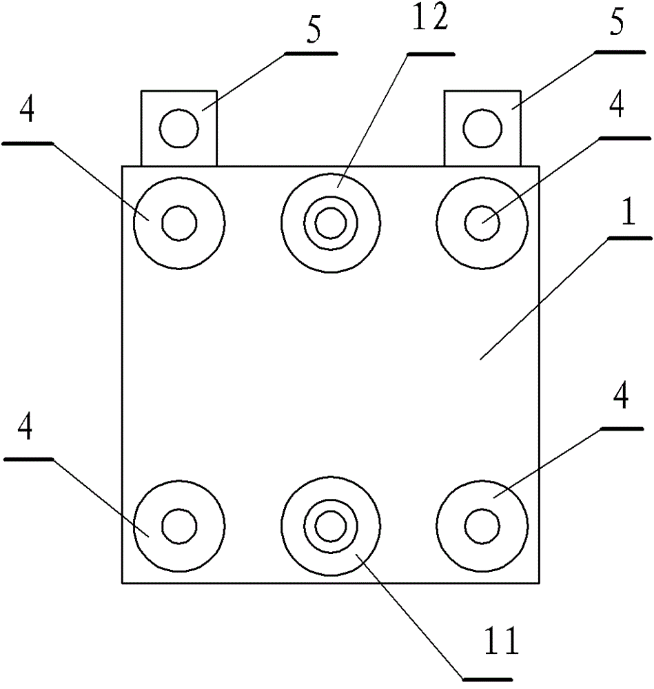
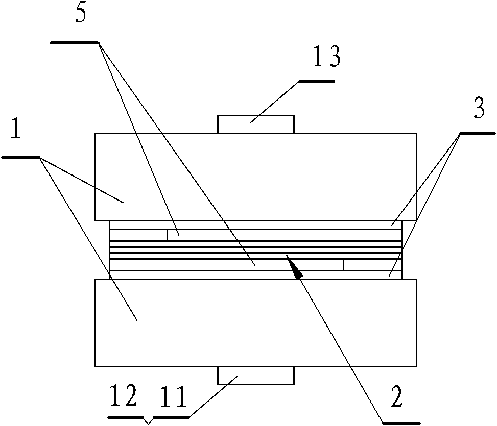
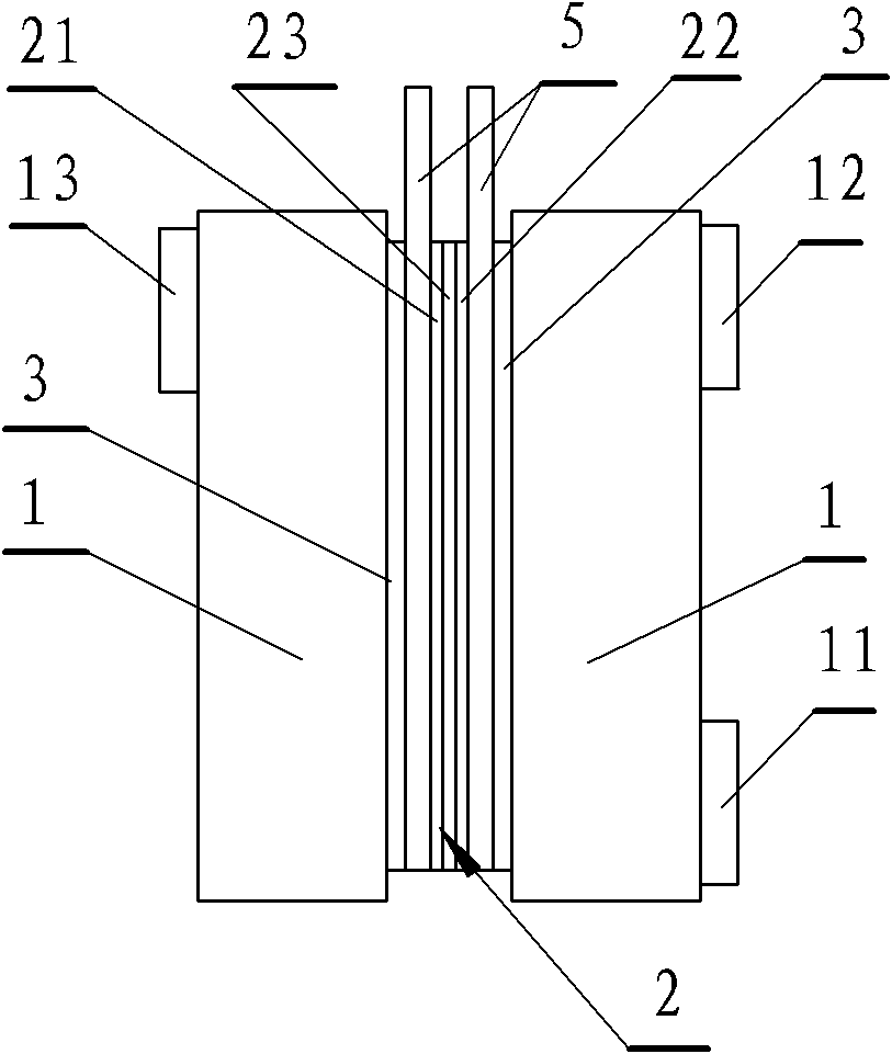
[0024] Such as Figures 1 to 3 and Figure 7 As shown, the electro-oxidation ozone generator of the present invention comprises the housing 1 of the electrolytic cell, the core component electrolytic electrode 2, and is formed by adding the gasket 3 and the fastener 4. The housing 1 is composed of two parts, and the middle clamp The inner cavity of the housing 1 is divided into an anode area and a cathode area by the electrolysis electrode 2. The upper part of the anode area is provided with an oxygen and ozone discharge port 12, and the lower part is provided with an electrolyte inlet 11. The upper part of the cathode area side is The hydrogen discharge port 13 provided, certainly the electrolytic solution import port 11 can be opened in the anode area and the cathode area and they are connected with a connecting pipe. The electrolysis electrode 2 then consists of an anodic membrane permeation electrode 21, a cathode membrane permeation electrode 22, an ion exchange membrane...

Embodiment 2

[0030] Such as Figures 4 to 7 As shown, the electro-oxidation ozone generator of the present invention comprises the housing 1 of the electrolytic cell, the core component electrolytic electrode 2, and is formed by adding the gasket 3 and the fastener 4. The housing 1 is composed of two parts, and the middle clamp The inner cavity of the housing 1 is divided into an anode area and a cathode area by the electrolysis electrode 2. The upper part of the anode area is provided with an oxygen and ozone discharge port 12, and the lower part is provided with an electrolyte inlet 11. The upper part of the cathode area side is The hydrogen discharge port 13 provided, certainly the electrolytic solution import port 11 can be opened in the anode area and the cathode area and they are connected with a connecting pipe.

[0031] The electrolysis electrode 2 is composed of an anodic membrane permeation electrode 21, a cathode membrane permeation electrode 22, an ion exchange membrane 23 sand...


PUM

PropertyMeasurementUnit
thicknessaaaaaaaaaa
thicknessaaaaaaaaaa

Abstract

The invention relates to an electro-oxidation ozone generator. It includes the shell that constitutes the electrolytic cell and the core component of the electrolytic electrode. The core component of the electrolytic electrode is composed of an anode membrane permeation electrode, a cathode membrane permeation electrode, and an ion exchange membrane sandwiched between the anode membrane permeation electrode and the cathode membrane permeation electrode. The membrane permeation electrode consists of a microporous plate base layer covered on the base layer and a multifunctional dynamic membrane layer on the surface of the middle layer. The cathode membrane permeation electrode is composed of a microporous plate base layer plus an intermediate layer and a device It is composed of a multifunctional dynamic film layer on the surface of the middle layer, or is composed of a microporous plate base layer and a multifunctional dynamic film layer arranged on the surface of the microporous plate base layer. It has the following characteristics: 1. Using the selective permeation function membrane to infiltrate the electrode, effectively control the penetration of the raw material liquid to the catalyst side, realize the balanced two-way permeation effect, reduce the resistance and energy consumption of the generator, and improve the efficiency. 2. The controllable internal pressure structure and self-balancing gas phase transmission channel ensure that the electrode reaction is carried out under controllable pressure, so that the gas precipitated from the anode has an ozone concentration of > 20%, and the ozone generation efficiency is high. Third, the equipment is simple to manufacture and low in cost.

Description

technical field [0001] The invention belongs to an electrochemical oxidation ozone generation device, in particular to an electro-oxidation ozone generator with a controllable internal pressure structure and a dynamic catalytic film layer at the gas generation part. Background technique [0002] Using water or water-based electrolyte as raw material, an ozone-oxygen mixed gas with a certain concentration can be obtained at the anode through an electrolysis device (ozone generator). Compared with the corona method, the electrochemical method has the characteristics of low voltage, high ozone concentration, and the generated gas does not contain harmful components such as NO3, so it is widely used in drinking water treatment, medical sanitation, sewage treatment, industrial bleaching, etc. There are obvious advantages in application. [0003] The electrolytic ozone generation technology emerged in the 1980s, and there have been many research and application reports. Generall...

Claims


Application Information

Patent Timeline
Patent Type & Authority Patents(China)
IPC IPC(8): C25B9/10C25B1/13C25B11/03C25B11/06C25B9/23
Inventor 王龙耀赵建洪王岚陈群何明阳于尔根·施努尔
Owner CHANGZHOU UNIV
Why Eureka
Try Eureka