System for Young modulus measurement of film

A Young's modulus and thin film technology, which is applied in the field of thin film Young's modulus measurement system, can solve the problems of difficult to apply to the ultra-clean environment of integrated circuits, samples with high porosity, and samples with low reflection coefficients, etc., and achieves the scope of application. Wide, high signal-to-noise ratio, the effect of simplifying the measurement process

Inactive Publication Date: 2012-11-07
TIANJIN UNIV
View PDF5 Cites 14 Cited by
  • Summary
  • Abstract
  • Description
  • Claims
  • Application Information

AI Technical Summary

Problems solved by technology

[0004] Although the above two surface acoustic wave detection technologies are superior to other detection technologies in terms of thin film Young's modulus measurement, they have their own shortcomings in some special samples and special scene tests.
For example: the four-quadrant surface acoustic wave detection announced in the piezoelectric detection device based on PVDF piezoelectric film LSAW positioning (publication number: CN102252967A, publication date: November 23, 2011), although it improves the measurement to some extent Accuracy, but it is still a contact detection, it cannot be used to measure samples with soft materials and high porosity, and it is difficult to apply to the ultra-clean environment required in integrated circuits; LSAW positioning measurement system based on Sagnac interferometer (public number: CN102221397A, publication date: October 19, 2011), although the method of positioning first and detecting later can accurately locate the position of the surface acoustic wave in time, so as to perform higher-precision measurement, it is always based on optics Non-contact measurement, cannot be used to measure samples with low reflectance and high transparency, and is easily affected by interference such as noise in the environment

Method used


Image

  • System for Young modulus measurement of film
  • System for Young modulus measurement of film
  • System for Young modulus measurement of film

Examples


Embodiment 1

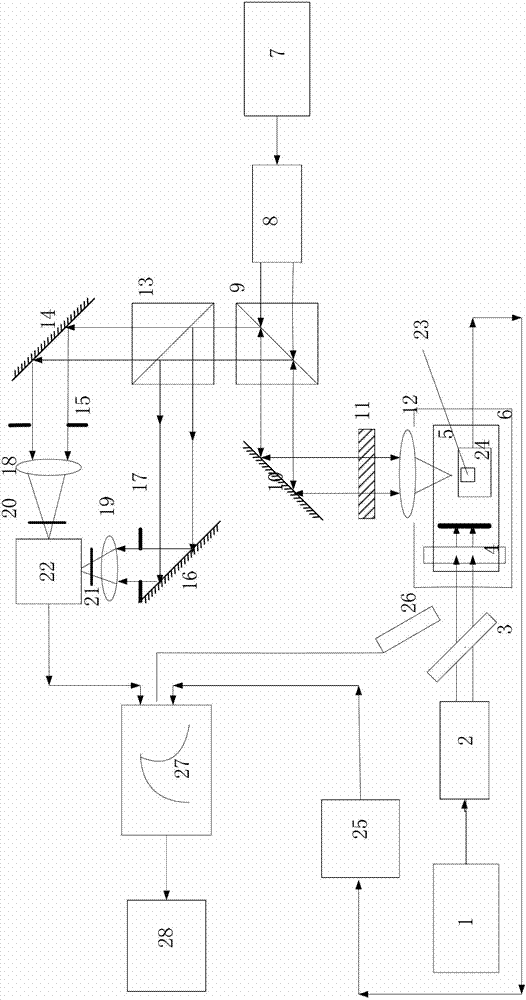
[0052] The working process of PVDF piezoelectric film surface acoustic wave detection through the first detection channel is as follows:

[0053] Pulse laser 1 emits pulse laser, which is collimated and expanded by first beam expander 2, and then divided into two parts by 3:7 beam splitter 3, 7 / 10 pulse laser and 3 / 10 pulse laser, and 7 / 10 pulse laser passes through the cylinder The focusing lens 4 is focused on the surface of the sample 5 to be tested to generate a surface acoustic wave signal; after the PVDF piezoelectric film detector 24 under the piezoelectric probe 23 detects the surface acoustic wave signal, the 3 / 10 pulse laser is used as a trigger signal to trigger the photoelectric The diode 26 outputs the electrical signal to the amplifier 25 via the wire through energy conversion, and the filtered and amplified signal reaches the oscilloscope 27 and finally enters the computer 28 for electrical signal processing.

Embodiment 2

[0055] The workflow of differential confocal SAW detection through the second detection channel is:

[0056] Pulse laser 1 emits pulse laser, which is collimated and expanded by first beam expander 2, and then divided into two parts by 3:7 beam splitter 3, 7 / 10 pulse laser and 3 / 10 pulse laser, and 7 / 10 pulse laser passes through the cylinder The focusing lens 4 focuses on the surface of the tested sample 5 to excite and generate a surface acoustic wave signal; the probe light emitted by the He-Ne laser 7 with a wavelength of 632.8nm is expanded and collimated by the first beam expander 8 and then 1:1 The polarizing beam splitter 910 is polarized so that the transmitted light therein is focused on the surface of the sample 5 to be tested after passing through the first plane reflector 10, the λ / 4 wave plate 11 and the first focusing lens 12, and then press the original path after obtaining the surface acoustic wave return. Due to passing through the λ / 4 wave plate twice, the ...

Embodiment 3

[0058] The working process of detecting PVDF piezoelectric thin film surface acoustic wave and differential confocal surface acoustic wave through the first detection channel and the second detection channel is as follows:

[0059] The first detection channel and the second detection channel should work at the same time. When adjusting, because the second detection channel is more complicated, the second detection channel should be adjusted first according to the actual situation, and then the first detection channel should be adjusted. The electrical signals detected by the first detection channel and the second detection channel can be displayed and stored on the oscilloscope 27 at the same time, and the test situation of the same tested sample 5 by the first detection channel and the second detection channel in the same environment can be visually compared .

[0060] Pulse laser 1 emits pulse laser, which is collimated and expanded by first beam expander 2, and then divided...


PUM

PropertyMeasurementUnit
wavelengthaaaaaaaaaa

Abstract

The invention discloses a system for Young modulus measurement of a film. The system comprises a pulsed laser, wherein the pulsed laser emits pulse laser, which is divided into 7/10 pulse laser and 3/10 pulse laser by a 3:7 spectroscope after being collimated and broadened by a first beam expander, and the 7/10 pulse laser is focused on the surface of a sample under test through a cylinder focusing lens to generate an acoustic surface wave signal under excitation; and the acoustic surface wave signal is converted into an electrical signal through a first detection channel and/or a second detection channel, and the electrical signal is output to a computer for processing after being displayed by an oscillograph. The system not only has the advantages of large signal amplitude, high applicability in testing environment with large disturbance and the like of the piezoelectric laser acoustic surface wave detection technology, but also inherits the advantages of rapid, accurate and non-contact measurement and high signal to noise ratio and the like of the difference confocal laser acoustic surface wave detection technology; and the system has higher applicability and wider range of applicability. Meanwhile, based on the advantage of high measurement bandwidth of the difference confocal laser acoustic surface wave detection technology, the measurement resolution is greatly improved.

Description

technical field [0001] The invention relates to the field of measuring Young's modulus of thin films by laser ultrasonic technology, in particular to a system for measuring Young's modulus of thin films. Background technique [0002] In recent years, laser ultrasonic technology has attracted extensive attention in the measurement of mechanical properties such as Young's modulus of thin films. In laser ultrasonic systems, surface acoustic wave detection technologies have emerged in an endless stream. In the current technology, piezoelectric laser surface acoustic wave detection technology based on PVDF (polyvinylidene fluoride) film is widely used. PVDF piezoelectric film has good acoustic impedance matching characteristics, large response bandwidth, and high electromechanical conversion sensitivity. , so that the piezoelectric laser surface acoustic wave detection system based on PVDF film has a measurement bandwidth much higher than that of the general optical detection sys...

Claims


Application Information

Patent Timeline
Patent Type & Authority Applications(China)
IPC IPC(8): G01N21/17
Inventor 丹特·多伦雷杨斐陈琨路子沫李艳宁傅星胡小唐
Owner TIANJIN UNIV
Why Eureka
Try Eureka