Combined removal device and method for sulphur, mercury and nitrate in smoke

A combined removal and flue gas technology, applied in the field of combined removal of nitrate, mercury, and sulfur in flue gas, can solve the problems of weakening economy, high cost, and failure to recycle mercury elements, so as to reduce investment costs, Reduce dosage, good effect

Active Publication Date: 2012-12-19
XI AN JIAOTONG UNIV
View PDF9 Cites 9 Cited by
  • Summary
  • Abstract
  • Description
  • Claims
  • Application Information

AI Technical Summary

Problems solved by technology

However, this technology chooses lye as the absorbent, even if the removal efficiency of pollutants is high, considering the large amount of CO in the flue gas 2 , SO 2 and NO x , the cost would be very high and greatly weaken the economics of the technology; there is no recycling of elemental mercury

Method used


Image

  • Combined removal device and method for sulphur, mercury and nitrate in smoke
  • Combined removal device and method for sulphur, mercury and nitrate in smoke
  • Combined removal device and method for sulphur, mercury and nitrate in smoke

Examples


Embodiment 1

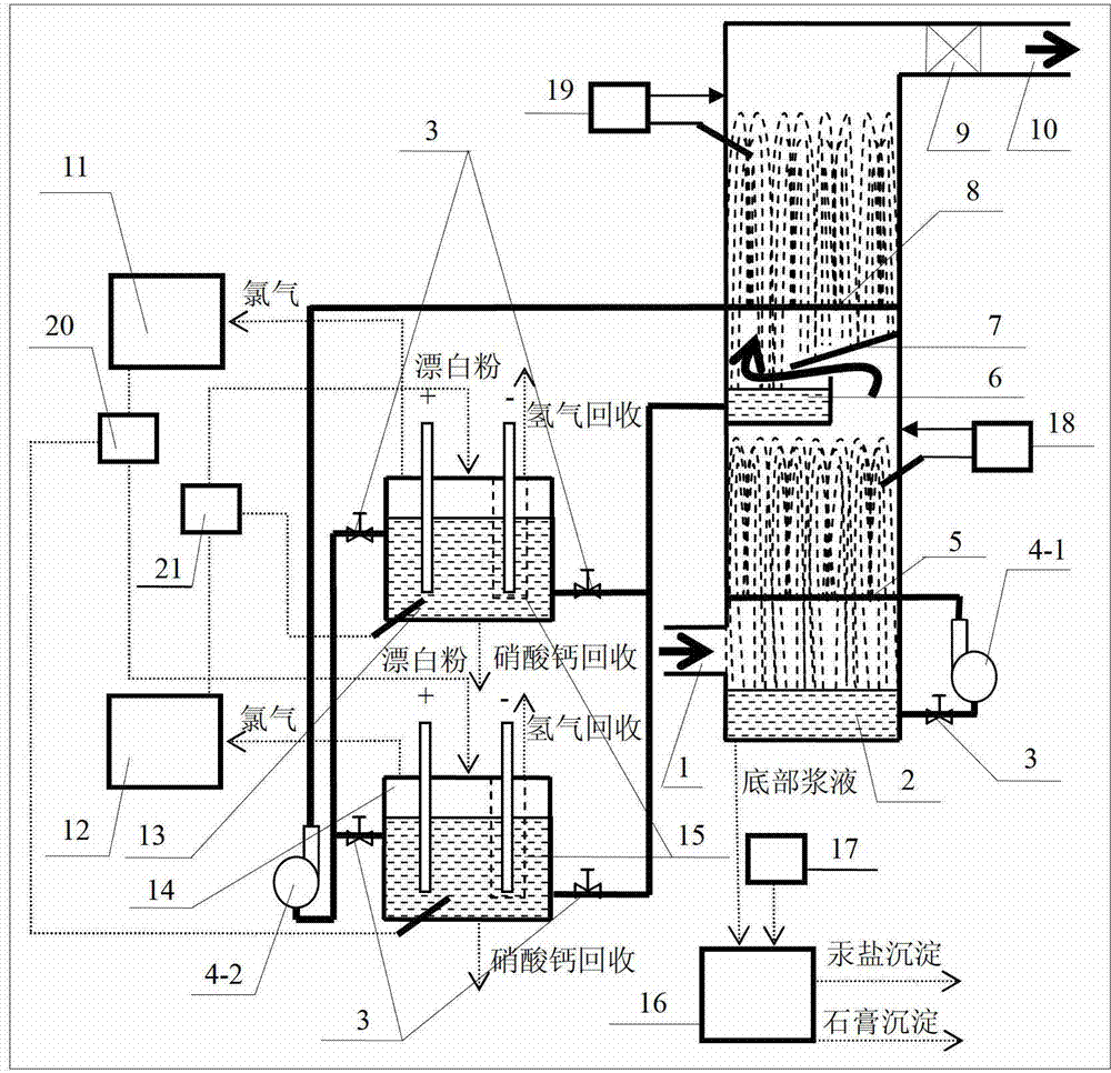
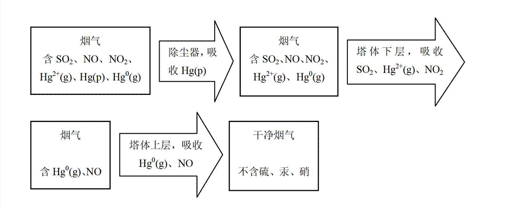
[0038] Tower part: This part is divided into two layers to remove pollutants in the flue gas. The dust from the dust collector contains SO 2 , NO, NO 2 , Hg 2+ (g) and Hg 0 (g) The flue gas at 90-120°C enters the lower layer of the tower body from the flue gas inlet 1, and the desulfurizing agent slurry in the desulfurizing agent slurry pool 2 is controlled at 5.8-6.2 by the first pH online monitoring feedback adjustment device 18 In between, the desulfurizer slurry is regulated by the flow control valve 3, and is transported to the desulfurizer slurry spray pipe 5 by the desulfurizer slurry circulation pump 4-1, and the desulfurizer slurry spray pipe 5 is sprayed upward to form a liquid curtain, and the flue gas Contact with the liquid curtain to generate mass transfer and reaction, and remove SO in the flue gas 2 , NO 2 and Hg 2+ (g). Contains NO and Hg at this time 0 The flue gas of (g) continues upwards, and the space between the oxidant slurry tank 6 and the oxida...

Embodiment 2

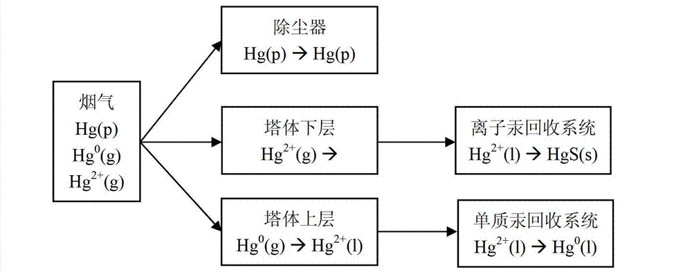
[0070] In the first electrolytic cell 13 or the second electrolytic cell 14 in embodiment 1, the oxidant slurry in the upper layer of the tower body oxidizes NO and Hg 0 At the same time as (g), it is in the state of continuous energization and electrolysis. The working process of this embodiment is similar to that of embodiment 1, and the difference with embodiment 1 is: in the flue gas Hg 0 (g) When the concentration is low, the first electrolytic cell 13 or the second electrolytic cell 14 does not conduct electrified electrolysis until the Hg in the oxidizing agent slurry 2+ (l) After accumulating to a certain concentration, then energize and electrolyze out Hg 0 (l), which can save power consumption compared with continuous energization electrolysis.


PUM


Abstract

Disclosed are combined removal device and method for sulphur, mercury and nitrate in smoke. The device comprises a sulphur removal system, a combined mercury-nitrate removal system, a mercury ion recovery system, an elementary mercury recovery system, and an oxidant regeneration system. The sulphur removal system is disposed on the lower portion of a column. The combined mercury-nitrate removal system is disposed on the upper portion of the column. The mercury ion recovery system is connected with the bottom of the sulphur removal system. The elementary mercury recovery system is connected with the combined mercury-nitrate removal system. The oxidant regeneration system is connected with the elementary mercury recovery system. The removal method includes smoke purification, mercury atom recovery and chlorine atom recycling. The removal device and method have the advantages that the structure is simple, integrity is high, operational cost is low, materials are recycled, and byproducts can be recycled.

Description

technical field [0001] The invention belongs to the technical field of flue gas purification, and in particular relates to a combined removal device for sulfur, mercury and nitrate in flue gas and a removal method thereof. Background technique [0002] Sulfur, mercury, and nitrate are the main pollutants in the flue gas of power plant boilers. Sulfur and nitric acid form acid rain, and mercury is a highly toxic heavy metal element. The environmental and health problems caused by these pollutants are increasingly affecting the sustainable development of the national economy and human health. [0003] At present, the mainstream desulfurization technology is limestone gypsum wet flue gas desulfurization (WFGD), which has mature technology, high removal efficiency and reliable process, and is the only large-scale commercial application desulfurization method in the world; Hg in air 2+ (g) and NO 2 , but does not absorb NO and Hg 0 (g), so far from NO x and Hg control requi...

Claims


Application Information

Patent Timeline
Patent Type & Authority Applications(China)
IPC IPC(8): B01D53/80B01D53/60B01D53/64B01D50/00C22B43/00
CPCY02P10/20
Inventor 李娜陈潞周屈兰常彦张勇胡斌
Owner XI AN JIAOTONG UNIV
Why Eureka
Try Eureka