Biomass extruding and molding combined unit

A technology of extrusion molding and combined unit, which is applied in the direction of material forming presses, presses, manufacturing tools, etc., can solve the problems that cannot be achieved, the power transmission distance is long, and the axial shear thickness, hardness, and uniformity cannot be achieved. scale, length etc.

Inactive Publication Date: 2013-01-09
吴昊
View PDF5 Cites 13 Cited by
  • Summary
  • Abstract
  • Description
  • Claims
  • Application Information

AI Technical Summary

Problems solved by technology

[0004] 1. The extrusion wheel of the parallel extrusion and ring extrusion mechanism rotates once with the main drive shaft and can only perform tangential extrusion movement with gaps in the small area and small dose of one pair or two pairs of holes in an instant, directly and effectively. Less, high no-load ratio, and a lot of waste of functions
[0005] 2. The power unit is a motor of 30KW or more than 50KW, and the power transmission distance from the power transmission mechanism to the extrusion wheel is relatively long.
The rolling bearing of the squeeze wheel is difficult to achieve no gap dustproof sealing protection, and it is difficult to replenish lubricating grease and heat dissipation
[0007] 4. The extrusion of the extrusion wheel and the die set of the flat die plate and the ring die plate is tangential extrusion instead of axial extrusion, which requires large force and low efficiency, and there is no manual or automatic extrusion gap. Randomly adjust the mechanism device for compensating the extrusion, so the extrusion cannot be kept in the best clearance condition, so the extrusion

Method used


Image

  • Biomass extruding and molding combined unit
  • Biomass extruding and molding combined unit
  • Biomass extruding and molding combined unit

Examples


Embodiment Construction

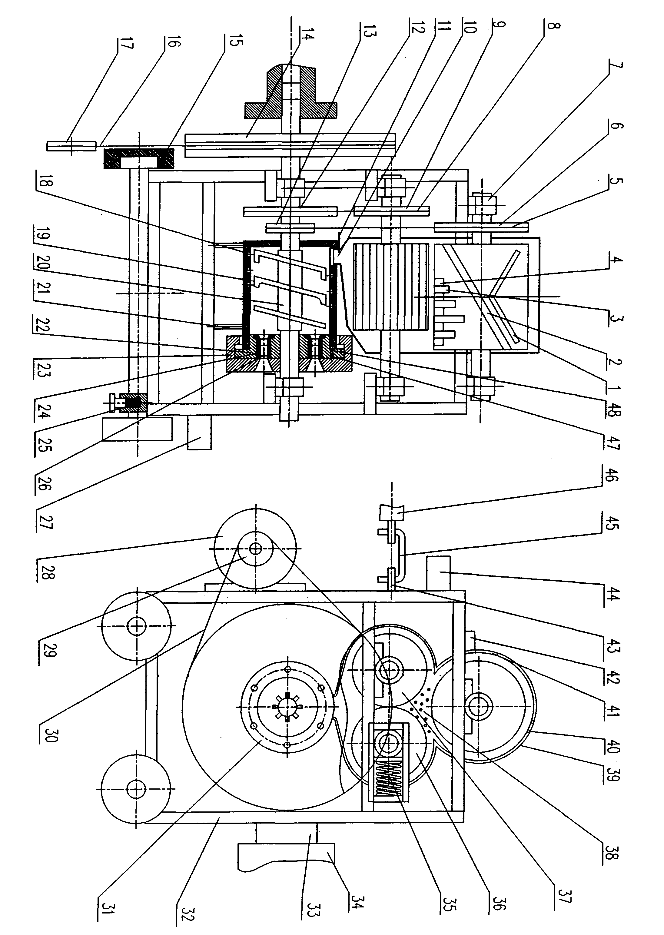
[0064] 1. Manufacture the frame according to mechanical design, manufacturing regulations and standards, mold design and manufacturing standards, and the technical scheme of the present invention, and after aging, process the reference plane again, and ensure the non-parallelism, non-perpendicularity, surface roughness requirements.

[0065] 2. According to the precision requirements of the gear meshing, the gear pair is made, and the overload protection device of the spring automatically adjusts and compensates the gap.

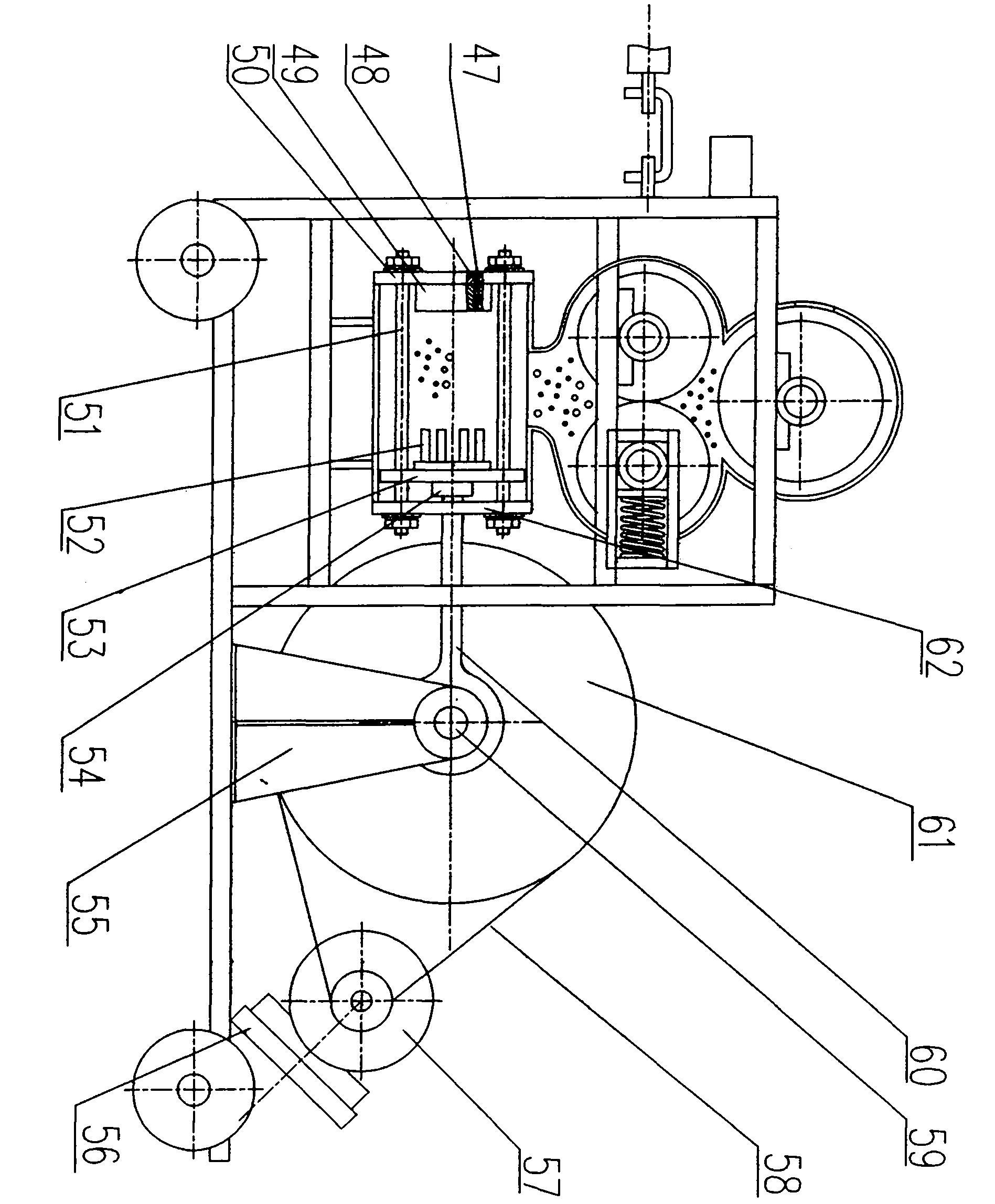
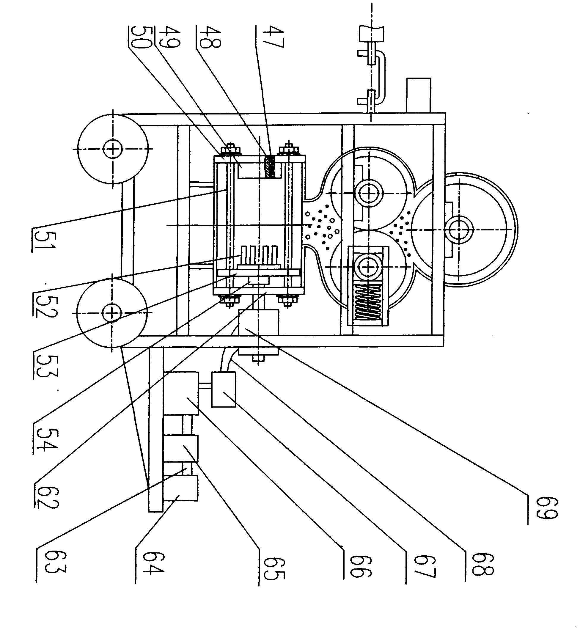
[0066] 3. Install the extrusion template on the extrusion barrel and the support plate of the D plan and the E plan according to the precision of the manufacturing mold.

[0067] 4. Install the extrusion disconnecting device on the extrusion molding mechanism on the extrusion template according to the required clearance, non-parallelism, and non-perpendicularity requirements.

[0068] 5. According to the hardness, precision and clearance required for sheari...


PUM


Abstract

The invention relates to a biomass extruding and molding combined unit which is formed by a power device, an operation control device, a cutting device, a rolling device, an extruding and molding device, a finished-product squeezing and cutting-off device and a weighing and packaging mechanism device and is mounted on the same rack. The biomass extruding and molding combined unit can continuously make biomasses including fine and soft rice and wheat straws, rough and hard bamboo, wood, cotton and bean stalks, palms, sugarcanes, rattans, potato rattans, corn cores, stalks and the like into molded products. Particularly, a gear pair is used for carrying out repeated S-shaped rolling on the materials after the materials pass through a gear top, a gear surface and a gear root to be cracked in a radial direction, so that elastic stress is degraded, and a gap is manufactured for contained sugar and lignin to be thermalized and smelted until a thin-sheet-wire net shape is formed and the softening is realized; and in a squeezing process, residual elastic stress can be degraded, a porous hollow molded block in a single-hole pipe shape or a coal ball shape can be extruded by sufficient and uniform yielding and deformation, and dense adhesion, or a spiral and straight convex rib is extruded or a circular and non-circular molded block of a groove is extruded. Particularly, the invention provides the biomass extruding and molding combined unit which is mounted on a combined harvesting machine and takes power to link or walk along with the combined harvesting machine.

Description

[0001] The invention relates to a device for processing renewable biomass materials, which is composed of power, operation control, shearing, rolling, extrusion molding, finished product extrusion and disconnection, and weighing and packaging mechanisms, and is installed on the same frame. Agglomerated into fuel blocks to generate energy, to partially replace non-renewable coal, oil, and natural gas in a biomass extrusion unit. Background technique [0002] Biomass blocks (briquetting for short) in the background technology are made by extrusion molding machines with flat (straight) extrusion and ring (side) extrusion mechanisms (with an electric control box, briquetting machine for short). The briquetting machine also needs a front-mounted cutting mill and a belt conveyor to form a system production capacity, so it cannot achieve continuous joint work, and it occupies a large area, the matching between power and machinery is poor, and the power waste is large. [0003] There ...

Claims


Application Information

Patent Timeline
IPC IPC(8): B30B11/24B30B11/26B30B15/00
Inventor 不公告发明人
Owner 吴昊
Why Eureka
Try Eureka