Composite microneedle array including nanostructures thereon

A microneedle array, nanostructure technology, applied in fields such as

Active Publication Date: 2013-03-06
SORRENTO THERAPEUTICS INC
View PDF47 Cites 17 Cited by
  • Summary
  • Abstract
  • Description
  • Claims
  • Application Information

AI Technical Summary

Problems solved by technology

[0006] Unfortunately, even if microneedles are included on transdermal devices, transdermal devices are currently limited to the delivery of low molecular weight agents with moderate lipophilicity and no electrical charge.

Method used


Image

  • Composite microneedle array including nanostructures thereon
  • Composite microneedle array including nanostructures thereon
  • Composite microneedle array including nanostructures thereon

Examples


example 1

[0177] A variety of different molds are prepared using photolithographic techniques similar to those used to design and fabricate circuits. The individual process steps are generally known and described in the art.

[0178] Initially, silicon substrates were prepared by cleaning with acetone, methanol, and isopropanol, and then a 258 nanometer (nm) silicon dioxide layer was deposited according to a chemical vapor deposition process.

[0179] Each substrate was patterned by an electron beam exposure patterning process known in the art using a JEOL JBX-9300FSEBL system. The process conditions are as follows:

[0180] Beam current=11nA

[0181] Acceleration voltage = 100kV

[0182] Shooting pitch=14nm

[0183] Dose=260μC / cm 2

[0184] Resist = ZEP520A, ~330nm thickness

[0185] Developer = n-pentyl acetate

[0186] Developing time = 2 minutes of immersion, 30 seconds followed by isopropanol rinse.

[0187] The silicon dioxide etch is then performed by STS Advanced Oxide ...

example 2

[0201] Films were formed as described in Example 1, including various patterns, polystyrene (PS) or polypropylene (PP) formed. The underlying substrate thickness varies. The patterns utilized were DN2, DN3 or DN4 using the formation process described in Example 1. The patterned die is varied in hole depth and feature pitch to form a variety of different sized features in a specified pattern. Sample 8 (designated BB1 ) was formed by using a 0.6 μm microporous polycarbonate filter as a mold. A 25 μm polypropylene film was placed on top of the filter and then heated to melt to enable the polypropylene to flow into the pores of the filter. The mold was then cooled and the polycarbonate mold was dissolved by using dichloromethane solvent.

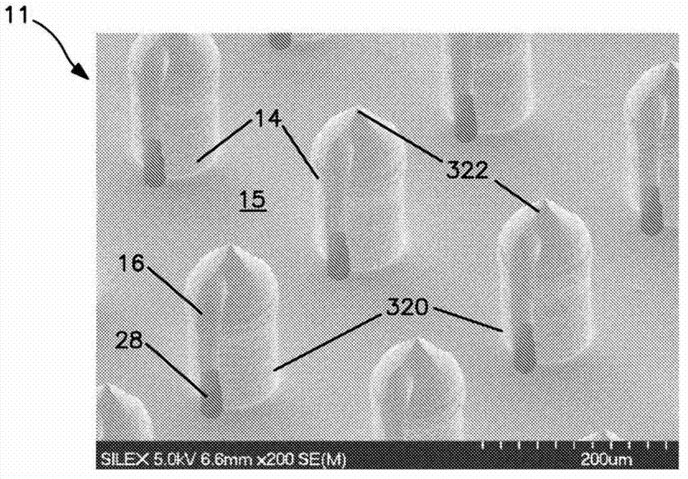
[0202] The resulting SEM is shown in Figure 28-36 , and the characteristics of the films formed are summarized in Table 3 below.

[0203] table 3

[0204]

[0205] 1 Pattern features are shown in the accompanying drawings

[0206] 2...

example 3

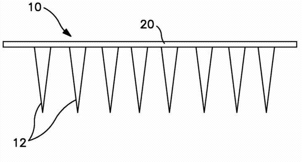
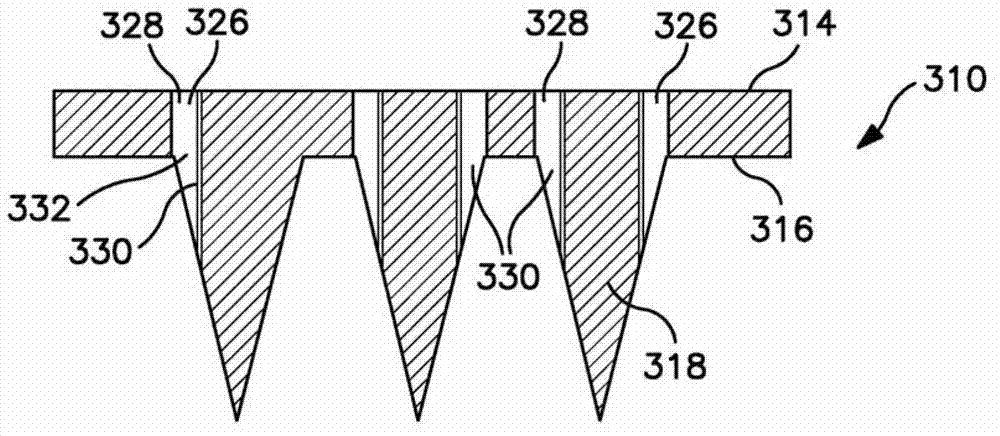
[0216] An array of microneedles is formed including a cover film defining a nanopatterned surface. Initially, arrays of microneedles are formed on silicon wafers through a photolithography process. Each needle includes two oppositely positioned side channels aligned with a perforation in the base of the needle.

[0217] Microneedles are formed on silicon substrates according to typical micromachining processes. The sheet is coated with a resist and / or oxide layer, followed by selective etching (oxide etch, DRIE etch, iso etch), debonding, deoxidation, and photolithographic techniques (e.g., iso lithography, aperture photolithography) according to standard methods. lithography, slit lithography) to form microneedle arrays.

[0218] After forming the microneedle array, a 5 μm polypropylene film including the DN2 pattern formed thereon, as described in Example 1 and characterized in Sample 2 of Table 3, was laid on the microneedle array. The sheet / film structure was kept in a ...


PUM

PropertyMeasurementUnit
sizeaaaaaaaaaa
heightaaaaaaaaaa
heightaaaaaaaaaa

Abstract

Disclosed are composite microneedles arrays including microneedles and a film overlaying the microneedles. The film includes a plurality of nano-sized structures fabricated thereon. Devices may be utilized for interacting with a component of the dermal connective tissue. A random or non-random pattern of structures may be fabricated such as a complex pattern including structures of differing sizes and/or shapes. Devices may be beneficially utilized for delivery of an agent to a cell or tissue. Devices may be utilized to directly or indirectly alter cell behavior through the interaction of a fabricated nanotopography with the plasma membrane of a cell and/or with an extracellular matrix component.

Description

[0001] Cross References to Related Applications [0002] This application claims U.S. Provisional Patent Application Serial No. 61 / 328,723 filed April 28, 2010, U.S. Provisional Patent Application Serial No. 61 / 411,071 filed November 8, 2010, and filed January 2011 Priority of U.S. Provisional Patent Application Serial No. 61 / 435,939 dated 25, the entire contents of which are incorporated herein by reference. Background technique [0003] The main methods of drug delivery include oral and injection, but these methods present difficulties. For example, injections can be painful and both methods tend to result in a burst of medicament rather than the preferred steady state administration. In addition, the long-term successful use of both oral and parenteral administration requires consistent compliance by the patient with the timing requirements of the method of administration. [0004] Transdermal drug delivery materials have been developed in an attempt to provide a painles...

Claims


Application Information

Patent Timeline
Patent Type & Authority Applications(China)
IPC IPC(8): A61M37/00A61M5/158
CPCA61K38/191A61M37/0015A61K9/7023A61M2037/003A61M2037/0061A61M2037/0053A61M2037/0023A61B17/205A61K9/0021Y10T156/10Y10T156/1057Y10T156/1039A61K38/1793A61P37/06A61M37/00A61M5/158A61M2037/0038B29C59/002B29C59/026B29C2059/023B29K2995/0056B29L2031/7544B29L2031/756
Inventor R·F·罗斯
Owner SORRENTO THERAPEUTICS INC
Why Eureka
Try Eureka