
Method and device for catalytic preparation of hydrogen from naphthenic hydrocarbon

A cycloalkane and catalyst technology, which is applied in the field of hydrogen production from organic liquids, can solve the problems of unsuitable large-scale hydrogen production, bulky reaction device, and poor reaction continuity, so as to improve the dehydrogenation reaction efficiency and improve the reaction efficiency Good efficiency and catalytic effect

Inactive Publication Date: 2013-04-17
ZHEJIANG UNIV
View PDF1 Cites 5 Cited by
  • Summary
  • Abstract
  • Description
  • Claims
  • Application Information

AI Technical Summary

Problems solved by technology

From a thermodynamic point of view, the catalytic dehydrogenation of organic liquids is an endothermic reaction, and high temperature is conducive to the occurrence of dehydrogenation reactions, while the highest temperature of the catalyst in liquid dehydrogenation reactions can only reach the boiling of the reactants, which is not conducive to the reaction.
From a kinetic point of view, the catalytic dehydrogenation of organic liquids is a reversible reaction, and the reverse reaction is easy to occur under the conditions of liquid dehydrogenation reaction, resulting in a decrease in the dehydrogenation effect.
Under the conditions of traditional dehydrogenation reaction technology, using P - t, Pd, Rh and other precious metals are extremely doped mixed catalysts, although good dehydrogenation effect can be obtained, but the catalysts are easy to coke and deactivate, and the continuity of the reaction is not good, and the catalysts are expensive, and the volume of the reaction device is relatively large. Suitable for large-scale hydrogen production applications

Method used


Image

  • Method and device for catalytic preparation of hydrogen from naphthenic hydrocarbon

Examples


Embodiment 1

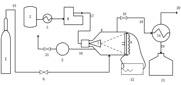
[0024] Take 3 g of catalyst Raney nickel, wash 3 times with absolute ethanol to replace the water therein, and press the catalyst into a circular sheet, then add it to a 50ml reactor and fix it at the bottom of the reactor; turn on the vacuum pump Vacuumize the reactor, turn off the vacuum pump, open the nitrogen bottle, feed nitrogen into the reactor, heat the bottom of the reactor under the protection of nitrogen, and slowly raise the temperature of the catalyst at a rate of 10°C / min to remove the combined catalyst in Raney nickel. Water and absolute ethanol, when the temperature rises to 160°C, the catalyst has been dried, at this time, the nitrogen flow is stopped, and the organic liquid condenser is opened to cool the cyclohexane to 6°C; the dehydrogenation reaction temperature is set to 326°C, and the reaction The bottom of the reactor was heated to the dehydrogenation reaction temperature. After the catalyst temperature was stabilized, the syringe pump was turned on, and...

Embodiment 2

[0026] Take 4.6g of catalyst Raney nickel, wash 3 times with absolute ethanol to replace the moisture therein, and press the catalyst into a circular sheet, then add it to a 50ml reactor, and fix it at the bottom of the reactor; turn on the vacuum pump Vacuumize the reactor, turn off the vacuum pump, open the nitrogen bottle, feed nitrogen into the reactor, heat the bottom of the reactor under the protection of nitrogen, and slowly raise the temperature of the catalyst at a rate of 10°C / min to remove the combined catalyst in Raney nickel. Water and absolute ethanol, when the temperature rises to 160°C, the catalyst has been dried, at this time, the nitrogen flow is stopped, and the organic liquid condenser is opened to cool the methylcyclohexane to 10°C; the dehydrogenation reaction temperature is set to 315°C, and The bottom of the reactor was heated to the dehydrogenation reaction temperature. After the catalyst temperature was stabilized, the syringe pump was turned on. Meth...

Embodiment 3

[0028] Take 7 g of catalyst Raney nickel (apparent density is about 3.0 g cm -3, with an average particle size of 16.58 μm), washed three times with absolute ethanol to replace the water in it, and pressed the catalyst into a circular thin layer, then added it to a 50ml reactor and fixed it at the bottom of the reactor; turned on the vacuum pump to drain the reactor Vacuumize, turn off the vacuum pump, open the nitrogen bottle, feed nitrogen into the reactor, heat the bottom of the reactor under the protection of nitrogen, and slowly raise the temperature of the catalyst at a rate of 10°C / min to remove bound water and free Water ethanol, when the temperature rises to 160°C, the catalyst has been dried, at this time stop nitrogen, open the organic liquid condenser to cool decahydronaphthalene to 2°C; set the dehydrogenation reaction temperature to 346°C, and heat the bottom of the reactor To the dehydrogenation reaction temperature, after the catalyst temperature is stabilized,...


PUM

PropertyMeasurementUnit
particle sizeaaaaaaaaaa

Abstract

The invention provides a method and a device for catalytic preparation of hydrogen from naphthenic hydrocarbon. The method comprises the following steps of: fixing a catalyst at the bottom of a reactor after the catalyst is washed by absolute ethyl alcohol; vacuumizing the reactor and introducing nitrogen into the reactor; heating the bottom of the reactor under nitrogen protection to ensure that the temperature of the catalyst slowly rises; stopping introducing the nitrogen after the catalyst is dried to open an organic liquid condenser; setting a dehydrogenation reaction temperature; heating the bottom of the reactor to be the dehydrogenation reaction temperature; injecting and feeding the naphthenic hydrocarbon at a constant velocity; discharging the generated hydrogen from the system after condensation and separation; and condensing the other steam components in a condenser and gathering the components into a product storage tank. By the method and the device, a precious metal catalyst is replaced by cheap raney nickel, so that the reaction cost is reduced, and the catalytic effect of the catalyst is good; the feeding is carried out in a jetting mode under a wet-and-dry multi-phase reaction condition, so that the dehydrogenation reaction efficiency is improved; and the gas is not needed to be carried or blown, the prepared hydrogen is high in purity and not needed to be separated again.

Description

technical field [0001] The invention relates to the field of hydrogen production from organic liquids, in particular to a method and device for continuously dehydrogenating naphthenes by using a catalyst under "wet-dry" multiphase reaction conditions to produce hydrogen. Background technique [0002] As a green energy, hydrogen energy has the advantages of being clean, renewable, rich in sources, and high utilization rate. At the same time, hydrogen energy is also widely regarded as the most potential new clean energy to replace fossil fuels. The development and utilization of hydrogen energy can also alleviate the excessive emission of CO -2 resulting in the greenhouse effect. However, the volumetric energy density of hydrogen energy is very low. Therefore, finding a suitable hydrogen storage carrier to increase its energy density, and solving the hydrogen storage and depletion technology of the hydrogen storage carrier are important issues for the practical engineering a...

Claims


Application Information

Patent Timeline
Patent Type & Authority Applications(China)
IPC IPC(8): C01B3/02
Inventor 徐国华平浩梁寇智宁支尊欧吴富英宋林安越何潮洪
Owner ZHEJIANG UNIV
Learn More