

Supercharged three-phase absorbing type energy storage device
An absorption energy storage, three-phase technology, applied in the direction of adsorption machines, energy industry, heat storage equipment, etc., can solve the problems of affecting the absorption effect, inability to absorb, large pressure loss, etc., to improve efficiency and energy storage density, The significance of significant energy saving and emission reduction, the effect of increasing the heating temperature
- Summary
- Abstract
- Description
- Claims
- Application Information
AI Technical Summary
Problems solved by technology
Method used
Image

Examples
Embodiment 1
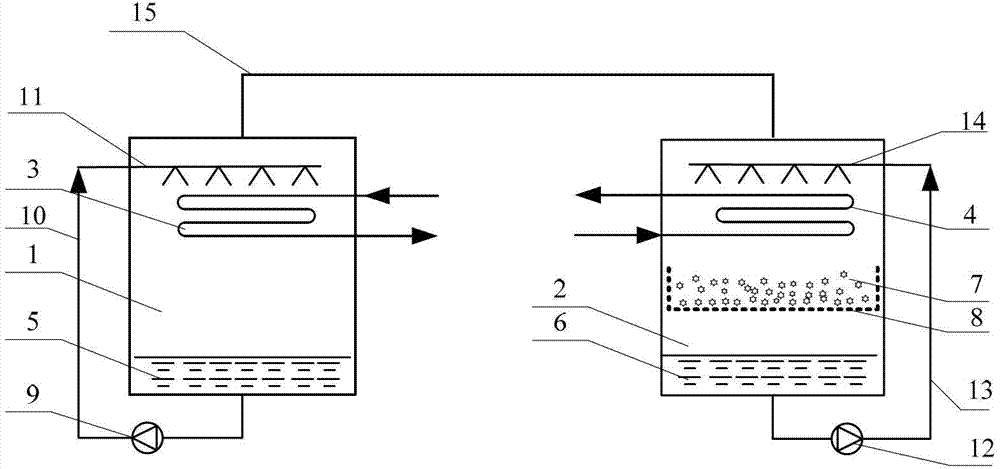
[0020] Embodiment 1: No pressurization process such as image 3 shown
[0021] The schematic diagram of the conventional energy storage or energy release process is as follows: image 3 As shown, the isolation valve 20 and the bypass valve 19 are opened, and the supercharger 16 and the reversing valve 17 are short-circuited.
[0022] When energy is stored, the solution 6 from the bottom of the solution tank 2 is sprayed onto the generator by the solution pump 12 through the solution circuit 13 and the solution spraying device 14 . The solution 6 desorbs the refrigerant vapor under the heating of the external driving heat source. The refrigerant vapor passes through the refrigerant vapor pipeline 15 and enters the condenser to condense. The condensed refrigerant is stored in the bottom of the refrigerant tank 1 in liquid form, and desorbed The final concentrated solution is then stored at the bottom of the solution tank 2. When the solution is continuously concentrated, the ...
Embodiment 2
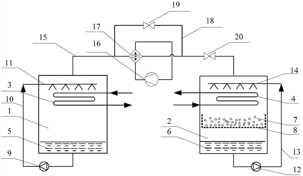
[0025] Embodiment 2: supercharging energy storage process such as Figure 4 shown
[0026] The supercharging energy storage process is as Figure 4As shown, open the isolation valve 20, close the bypass valve 19, the first heat exchanger 3 is used as a condenser, and the second heat exchanger 4 is used as a generator; the a port of the reversing valve 17 is connected with the refrigerant tank 1, The b port of the reversing valve 17 is connected with the gas outlet of the supercharger 16, and the c port of the reversing valve 17 is connected with the solution tank 2; the d port of the reversing valve 17 is connected with the air inlet of the supercharger 16; Port a of the valve 17 communicates with port b, and port c communicates with port d.
[0027] The solution 6 from the bottom of the solution tank 2 is sprayed onto the generator by the solution pump 12 through the solution circuit 13 and the solution spraying device 14 . The solution 6 desorbs the refrigerant vapor unde...
Embodiment 3
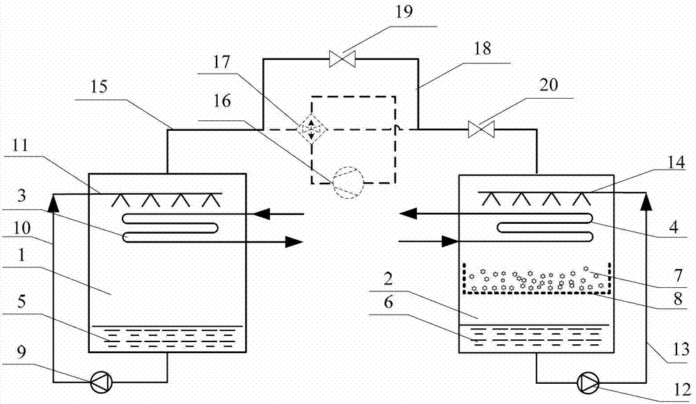
[0029] Embodiment 3: pressurized energy release process such as Figure 5 shown
[0030] The pressurized energy release process is as Figure 5 As shown, the first heat exchanger 3 is used as an evaporator, and the second heat exchanger 4 is used as an absorber; port a of the reversing valve 17 is connected to the refrigerant tank 1, and port b of the reversing valve 17 is connected to the supercharger The gas outlet of 16 links to each other, and the c port of reversing valve 17 links to each other with solution tank 2; The d port of reversing valve 17 links to each other with the air inlet of supercharger 16; The mouth is connected with the c mouth.
[0031] The refrigerant 5 from the bottom of the refrigerant tank 1 is sprayed onto the evaporator by the refrigerant pump 9 through the refrigerant circuit 10 and the refrigerant spraying device 11 , and the liquid refrigerant is heated and becomes refrigerant vapor to produce a cooling effect. The refrigerant vapor passes t...
PUM
 Abstract
Description
Claims
Application Information