

Metal surface micro texture group electrode direct writing micro electrolysis processing method and dedicated device
A metal surface and processing method technology, applied in the field of metal surface micro-texture group electrode direct writing micro-electrochemical machining, can solve the problems of complex process method, long processing cycle, tool wear, etc., to avoid tool wear, shorten processing cycle, The effect of good workpiece processing quality
- Summary
- Abstract
- Description
- Claims
- Application Information
AI Technical Summary
Problems solved by technology
Method used
Image

Examples
Embodiment 1
[0023] Example 1 The direct-writing micro-electrolytic machining method of metal surface micro-texture group electrodes includes the following steps:
[0024] 1) Using row-shaped group electrodes to process the micro-texture of the metal surface of the workpiece to be processed;
[0025] 2) Under the control of the numerical control system of the machine tool, the row-shaped group electrodes move relative to the workpiece to be processed. When the electrolyte is circulated and the processing power is turned on, the micro-texture is processed on the surface of the workpiece to be processed.
Embodiment 2
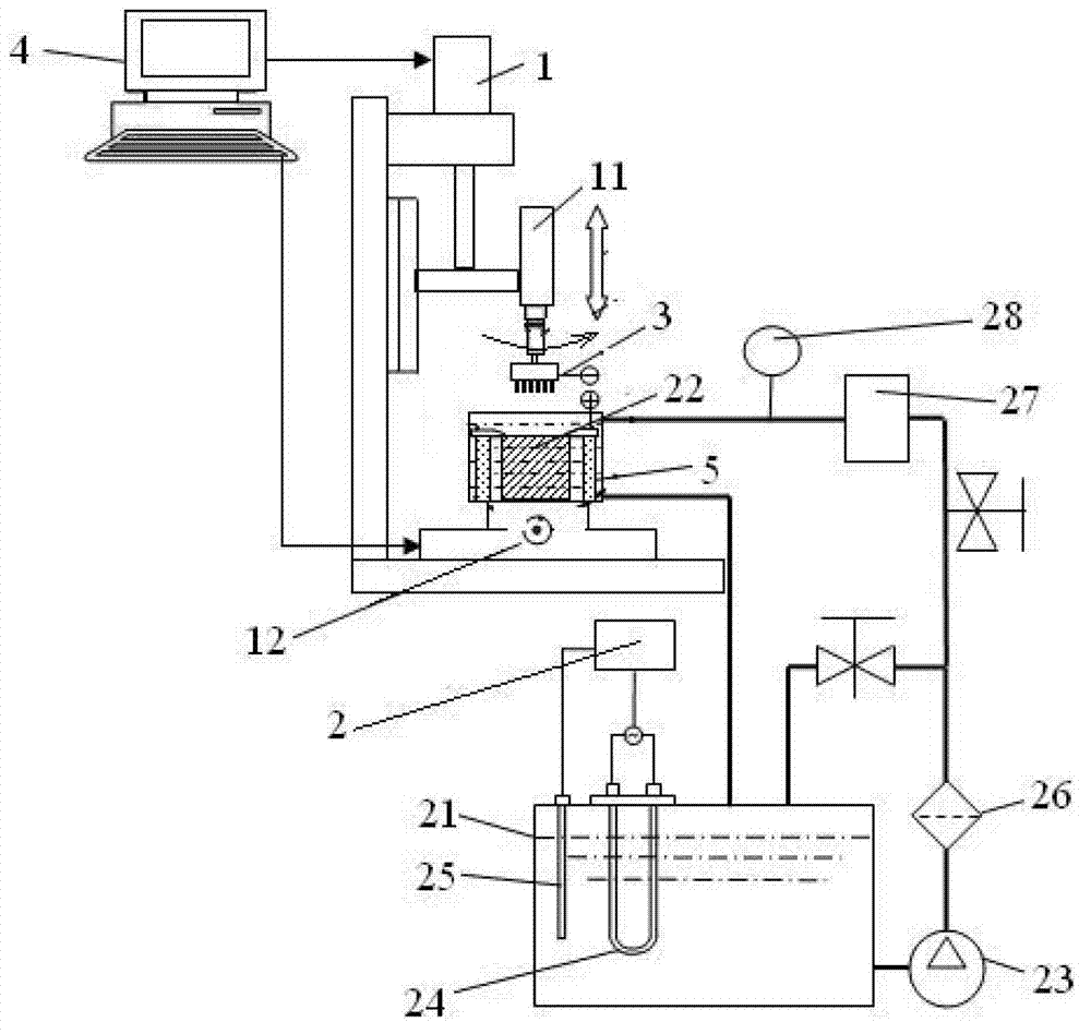
[0026] Embodiment 2 According to the special equipment of the processing method of embodiment 1, comprise machine tool 1, electrolyte circulation device 2, row shape group electrode 3, computer 4 and be equipped with the power supply of positive pole and negative pole, described machine tool 1, described Electrolyte circulation device 2 and described row-like group electrode 3 are all electrically connected with described computer 4, and are simultaneously controlled by the machine tool numerical control system configured in described computer 4; Described row-like group electrode 3 is according to The shape of the workpiece 5 to be processed is selectively installed on the main shaft 11 of the machine tool 1 or the electrolyte circulation device 2, and the row-shaped group electrodes 3 are electrically connected to the negative pole of the power supply, and the workpiece 5 to be processed Correspondingly installed on the electrolyte circulation device 2 or the main shaft 11 of...
Embodiment 3
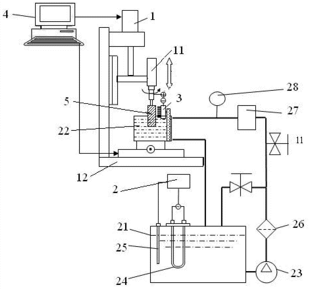
[0033] Embodiment 3 The difference between this embodiment and Embodiment 2 is that the workpiece 5 to be processed is a cylindrical structure, the row-shaped group electrodes 3 are installed in the electrolytic cell 22, and the workpiece 5 to be processed is installed on the spindle of the machine tool 1 11, the rest of the structure and implementation are the same as in Example 1.
[0034] The workpiece 5 to be processed is a cylindrical structure. At this time, the row-shaped group electrodes 3 are installed in the electrolytic cell 22, the workpiece 5 to be processed is installed on the main shaft 11 of the machine tool 1, and then the computer 4 is turned on, and the computer 4 is correspondingly turned on. CNC machine control system, after setting the corresponding parameters, connect the row group electrode 3 with the negative pole of the power supply, connect the workpiece 5 to be processed with the positive pole of the power supply, and start processing, and control th...
PUM
 Abstract
Description
Claims
Application Information