A laser scanning processing device

A laser scanning and processing device technology, which is applied in laser welding equipment, metal processing equipment, manufacturing tools, etc., can solve the problem of inability to achieve coaxial air blowing of static focused laser beams, etc.

Active Publication Date: 2015-11-04
张立国
View PDF6 Cites 0 Cited by
  • Summary
  • Abstract
  • Description
  • Claims
  • Application Information

AI Technical Summary

Problems solved by technology

Since the transmission direction of the laser beam focused by the galvanometer scanning is dynamic, there is no good way to blow air so that the airflow direction is consistent or basically consistent with the laser beam transmission direction, so as to suppress the generation of sparks and plasma generated by laser processing, so It has been impossible to achieve the above-mentioned coaxial air blowing effect of the static focused laser beam, and no one has solved this technical problem for many years

Method used


Image

  • A laser scanning processing device
  • A laser scanning processing device
  • A laser scanning processing device

Examples


Embodiment 1

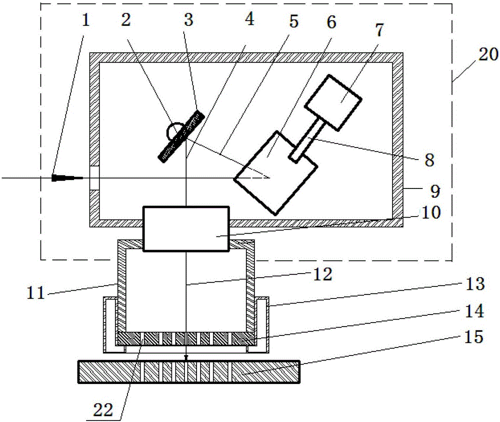
[0043] figure 1 Schematic diagram of the device structure for laser drilling of silicon wafers, such as figure 1 As shown: the silicon wafer laser drilling device includes a galvanometer scanning focusing module 20 , a positive pressure gas chamber 11 , a blowing mask plate 14 , and a negative pressure gas chamber 13 . The galvanometer scanning focusing module 20 includes a scanning galvanometer and a planar scanning focusing mirror 10 .

[0044] The scanning galvanometer includes a first mirror 6, a first motor 7 for driving the first mirror 6, a second mirror 3, a second motor for driving the second mirror 3, and a housing 9 for the scanning galvanometer The side of the scanning oscillating mirror housing facing the incident laser beam is provided with a laser entrance, and the first mirror 6, the first motor 7, the second mirror 3 and the second motor are located at the scanning oscillating Inside the mirror housing 9. The first mirror 6 of the scanning galvanometer is i...

Embodiment 2

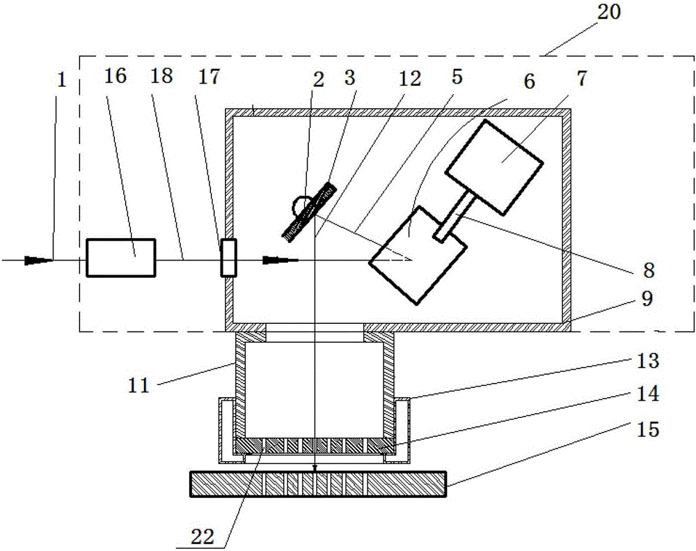
[0057] figure 2 Schematic diagram of the device structure for laser drilling of low-temperature co-fired ceramics, such as figure 2 As shown: the device for laser drilling of low temperature co-fired ceramics includes a galvanometer scanning focusing module 20 , a positive pressure gas cavity 11 , a blowing mask 14 and a negative pressure gas cavity 13 . The galvanometer scanning focusing module 20 includes a dynamic focusing mirror 16 and a scanning galvanometer.

[0058] The dynamic focusing mirror 16 has a wavelength of 1064 nm, a central focal length of 500 mm, and a focusing spot of 50 microns.

[0059] The scanning galvanometer includes a first mirror 6, a first motor 7 for driving the first mirror 6, a second mirror 3, a second motor for driving the second mirror 3, and a housing 9 for the scanning galvanometer . The first reflector 6 , the first motor 7 , the second reflector 3 and the second motor are located in the housing 9 of the scanning galvanometer. A lase...

Embodiment 3

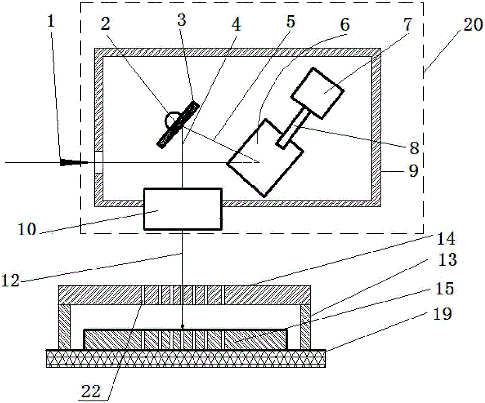
[0071] image 3 Schematic diagram of the device structure for laser drilling of copper sheets, such as image 3 As shown: the copper sheet laser drilling device includes a galvanometer scanning focusing module 20 , an air blowing mask 14 and a negative pressure gas chamber 13 , and the galvanometer scanning focusing module 20 includes a scanning galvanometer and a planar scanning focusing mirror 10 .

[0072] The scanning galvanometer includes a first mirror 6, a first motor 7 for driving the first mirror, a second mirror 3, a second motor for driving the second mirror 3, and a housing 9 for the scanning galvanometer, The first reflector 6, the first motor 7, the second reflector 3 and the second motor are located in the scanning galvanometer housing 9, and the scanning galvanometer housing is provided on the side facing the incident laser beam. The laser entrance, the first motor main shaft and the second motor main shaft are perpendicular to each other. The first mirror 6 ...


PUM

PropertyMeasurementUnit
diameteraaaaaaaaaa
wavelengthaaaaaaaaaa
poweraaaaaaaaaa

Abstract

The invention relates to a laser scanning processing device which comprises a galvanometer scanning focusing module, a positive pressure gas chamber and / or a negative pressure gas chamber, and an air-blowing mask template, wherein a distributed air-blowing ports are formed by presetting the thickness of the air-blowing mask template, the shapes of air flow windows and the like; and gas, of which the flowing direction is the same as or basically consistent with the transmission directions of lasers transmitting each of air flow windows, is formed by presetting gas pressure difference between a laser incidence surface and a laser emergent surface of the air-blowing mask template. The laser scanning processing device solves a difficult problem in distributed auxiliary air blowing of a galvanometer scanning focusing processing module during large-format laser processing, is a perfect solution of distributed auxiliary air blowing of a laser galvanometer scanning focusing processing method, and is particularly suitable for industrial mass production.

Description

technical field [0001] The invention relates to the field of laser processing, in particular to a laser scanning processing device with the function of controlling the space flow of auxiliary gas. Background technique [0002] Laser cutting produces a cloud of high-speed jet plasma and flying dust of the material being cut. The dust of these materials will seriously pollute and damage the focusing lens, and seriously affect the laser focus and laser cutting quality. At present, laser cutting machines adopt static focus and laser beam coaxial air blowing. The role of auxiliary air blowing in laser cutting is as follows: First, for the easily oxidized metal surface cut by metal laser cutting machines, oxygen blowing improves The absorption rate of laser light on the surface. When oxygen is blown during the laser heating process, the metal surface is rapidly oxidized, the reflectivity is rapidly reduced, and the reflection loss of the surface to the laser energy is reduced. ...

Claims


Application Information

Patent Timeline
Patent Type & Authority Patents(China)
IPC IPC(8): B23K26/36B23K26/142B23K26/082B23K26/064B23K26/00B23K26/06
Inventor 张立国
Owner 张立国
Why Eureka
Try Eureka