Embossed laser beam implementation method and device for reducing cracks on cladding layer
A technology of laser beam and implementation method, applied in optics, coatings, optical components, etc., can solve the problems of poor versatility, increased complexity of laser cladding system, low control accuracy, etc., to reduce temperature gradient and reduce cracking tendency , the effect of small thermal stress
- Summary
- Abstract
- Description
- Claims
- Application Information
AI Technical Summary
Problems solved by technology
Method used
Image

Examples
Embodiment 1
[0032] Preparation of NiCr-50%Cr on the surface of TC4 titanium alloy (Ti-6Al-4V) using a convex laser beam that can reduce cladding layer cracks 3 C 2 Coating, its specific steps are:
[0033]① Grinding, degreasing and sandblasting the surface of the TC4 titanium alloy substrate that has been wire-cut to a certain size;
[0034] ② Use the research body to mix NiCr and Cr with a ratio (mass fraction) of 1:1 3 C 2 The powder is ground and mixed, and the mixed powder is made into a paste with the binder cellulose ether, and evenly coated on the surface of the TC4 titanium alloy sample to be clad, the preset coating thickness is about 1.5mm;
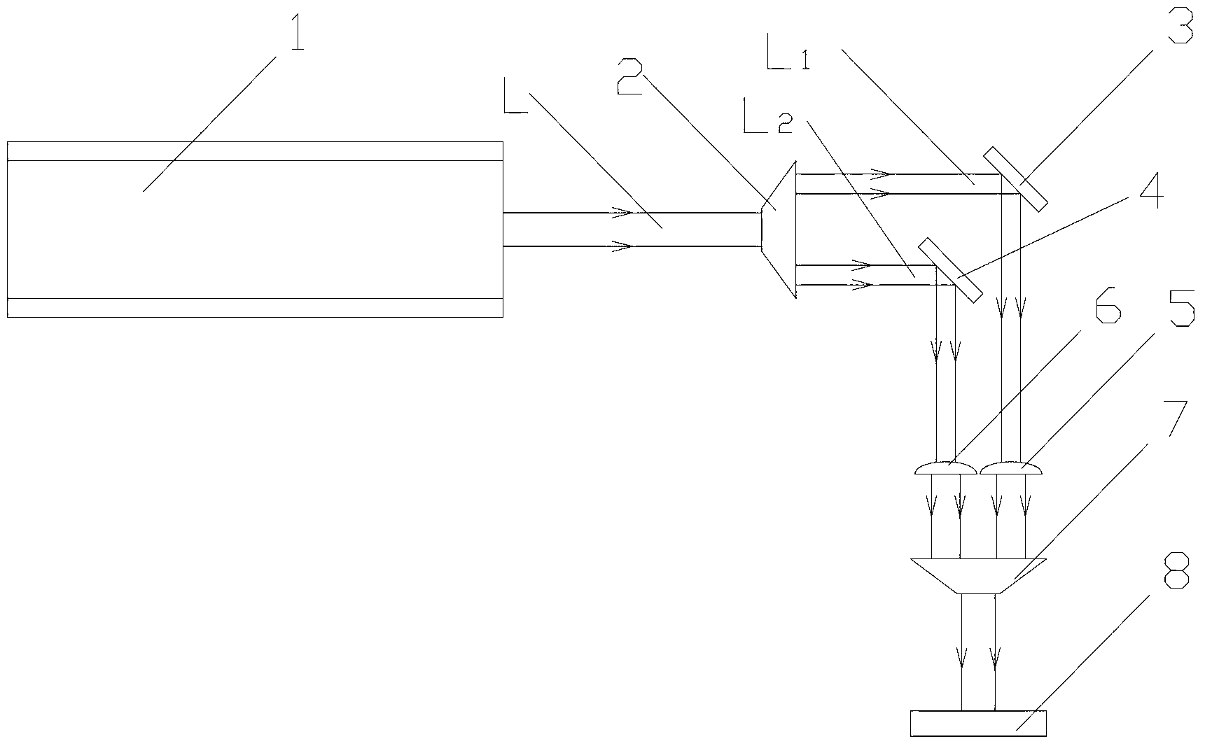
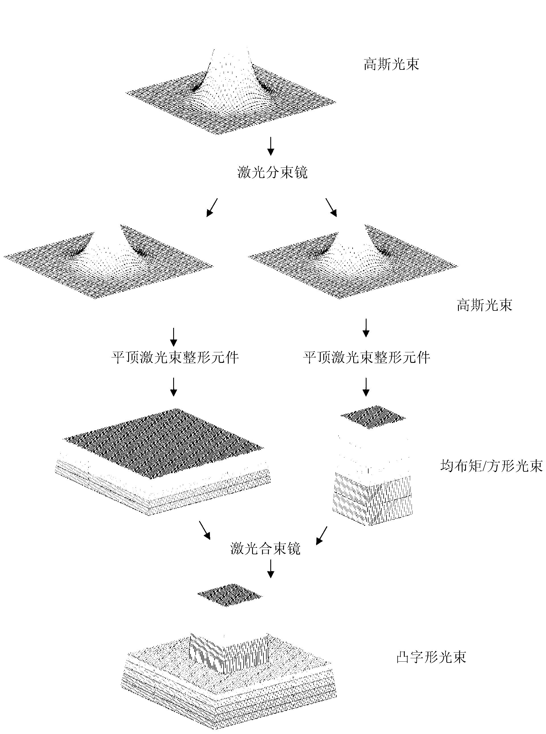
[0035] ③A laser beam splitter 2 with a fixed beam splitting ratio is used to split the laser beam emitted by the laser 1 into two laser beams L 1 , L 2 , the laser beam L 1 , L 2 Respectively reflected by the laser total reflection mirror 3, 4 to the flat-top laser beam shaping element 5, 6 to complete the transformation of the laser...
Embodiment 2
[0038] The NiCr-50%WC coating is prepared on the surface of the TiAl alloy substrate using a convex laser beam that can reduce cracks in the cladding layer. The specific steps are:
[0039] ① The surface of the TiAl alloy substrate is ground, degreased and sandblasted by WEDM to a certain size;
[0040] ② Grind and mix NiCr and WC powder with a ratio (mass fraction) of 1:1 with a grinder, make the mixed powder into a paste with binder cellulose ether, and apply it evenly on the surface of the TiAl alloy sample to be clad , the preset coating thickness is about 1.5mm;
[0041] ③A laser beam splitter 2 with a fixed beam splitting ratio is used to split the laser beam emitted by the laser 1 into two laser beams L 1 , L 2 , the laser beam L 1 , L 2 Respectively reflected by the laser total reflection mirror 3, 4 to the flat-top laser beam shaping element 5, 6 to complete the transformation of the laser power density, transforming it into two beams with a large size and a small...
Embodiment 3
[0044] Preparation of MCrAlY-5%Al on the surface of GH4033 nickel-based superalloy substrate using a convex laser beam that can reduce cladding layer cracks 2 o 3 Composite coating, its specific steps are:
[0045] ① Grinding, degreasing and sandblasting the surface of the GH4033 nickel-based superalloy substrate that has been wire-cut to a certain size;
[0046] ② Use the research body to mix MCrAlY and Al with a ratio (mass fraction) of 19:1 2 o 3 The powder is ground and mixed, and the mixed powder is made into a paste with the binder cellulose ether, and evenly coated on the surface of the GH4033 nickel-based superalloy sample to be clad, the preset coating thickness is about 1.5mm;
[0047] ③A laser beam splitter 2 with a fixed beam splitting ratio is used to split the laser beam emitted by the laser 1 into two laser beams L 1 , L 2 , the laser beam L 1 , L 2 Respectively reflected by the laser total reflection mirror 3, 4 to the flat-top laser beam shaping element...
PUM
| Property | Measurement | Unit |
|---|---|---|
| Thickness | aaaaa | aaaaa |
Abstract
Description
Claims
Application Information
 - Generate Ideas
- Intellectual Property
- Life Sciences
- Materials
- Tech Scout
- Unparalleled Data Quality
- Higher Quality Content
- 60% Fewer Hallucinations
Browse by: Latest US Patents, China's latest patents, Technical Efficacy Thesaurus, Application Domain, Technology Topic, Popular Technical Reports.
© 2025 PatSnap. All rights reserved.Legal|Privacy policy|Modern Slavery Act Transparency Statement|Sitemap|About US| Contact US: help@patsnap.com