Carbon nanometer tube field emitting cathode and manufacturing method thereof

A field emission cathode and carbon nanotube technology, applied in the field emission field, can solve the problems of small field emission current, unstable emission, weak bonding force between carbon nanotube layer and conductive substrate, etc.

Active Publication Date: 2013-12-18
SHENZHEN INST OF ADVANCED TECH CHINESE ACAD OF SCI
View PDF10 Cites 18 Cited by
  • Summary
  • Abstract
  • Description
  • Claims
  • Application Information

AI Technical Summary

Problems solved by technology

The problem with the electrophoresis method is that the bonding force between the carbon nanotube layer and the conductive

Method used


Image

  • Carbon nanometer tube field emitting cathode and manufacturing method thereof
  • Carbon nanometer tube field emitting cathode and manufacturing method thereof
  • Carbon nanometer tube field emitting cathode and manufacturing method thereof

Examples


preparation example Construction

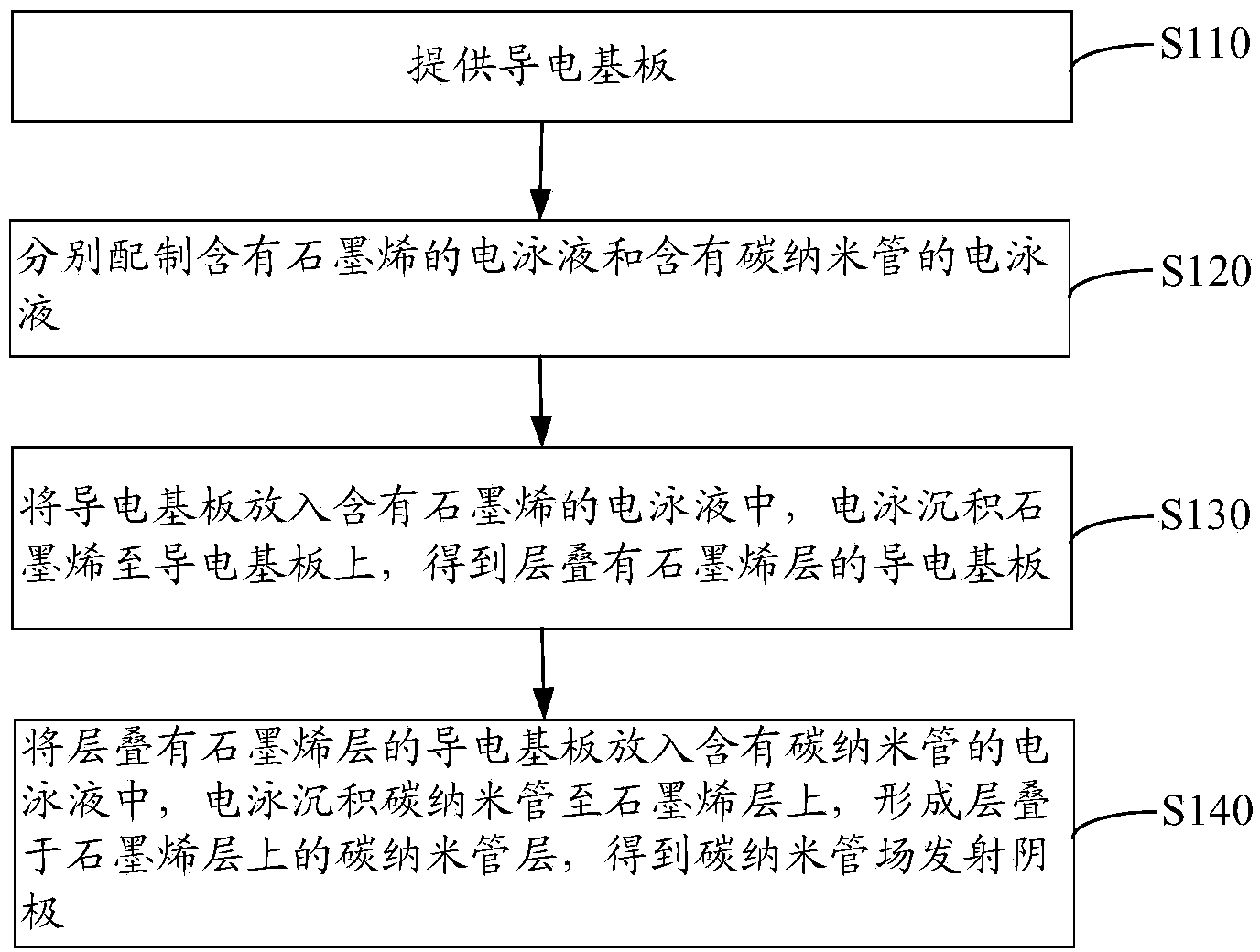
[0051] see figure 2 , the preparation method of the carbon nanotube field emission cathode of one embodiment, comprises the steps:

[0052] Step S110: providing a conductive substrate.

[0053] The conductive substrate can be a metal substrate such as a stainless steel substrate, a titanium substrate, a copper substrate, an aluminum substrate, a chromium substrate or a nickel substrate; or a metal substrate coated with tungsten, molybdenum, titanium, nickel, chromium, gold, silver or platinum Insulating substrate, wherein the insulating substrate is glass, ceramic or silicon wafer.

[0054] In another embodiment, the conductive substrate is ITO glass.

[0055] The conductive substrate was ultrasonically cleaned with acetone and ethanol for 10 minutes in sequence, and then dried with nitrogen gas for later use.

[0056] Step S120: Prepare graphene-containing electrophoretic fluid and carbon nanotube-containing electrophoretic fluid respectively.

[0057] The graphene and t...

Embodiment 1

[0094] Preparation of Carbon Nanotube Field Emission Cathode

[0095] (1) Add reduced graphene with a thickness of 1.1-3.7nm to absolute ethanol, and add 50% MgCl 2 (Based on the mass of graphene) as the first charge additive, the concentration of graphene is 0.05 mg / ml, ultrasonically dispersed for 1 hour, and an electrophoretic solution containing graphene is obtained;

[0096] (2) Add multi-walled carbon nanotubes with a diameter of less than 8 nm and a length of 5 to 15 μm in absolute ethanol, and add 25% MgCl 2 (Based on the mass of carbon nanotubes) as the second charge additive, the concentration of carbon nanotubes is 0.01 mg / ml, ultrasonically dispersed for 1 hour, and an electrophoretic solution containing carbon nanotubes is obtained;

[0097] (3) ITO glass was used as the conductive substrate, the conductive substrate was used as the cathode, and the oxygen-free copper sheet was used as the anode. Before use, it was ultrasonically cleaned with acetone and ethanol ...

Embodiment 2

[0101] Preparation of Carbon Nanotube Field Emission Cathode

[0102] (1) Add graphene oxide with a thickness of 5.0-8.6nm into absolute ethanol, and add 1% Mg(NO 3 ) 2 (Based on the mass of graphene) as the first charge additive, the concentration of graphene is 0.5 mg / ml, ultrasonically dispersed for 1 hour, and an electrophoretic solution containing graphene is obtained;

[0103] (2) Add single-walled carbon nanotubes with a diameter of less than 10-20 nm and a length of 10-20 μm into absolute ethanol, and add 1% Mg(NO 3 ) 2 (Based on the mass of carbon nanotubes) as the second charge additive, the concentration of carbon nanotubes is 0.1 mg / ml, ultrasonically dispersed for 3 hours, and an electrophoretic solution containing carbon nanotubes is obtained;

[0104] (3) The glass substrate deposited with a metal titanium layer was used as the conductive substrate, the conductive substrate was used as the cathode, and the stainless steel sheet was used as the anode. Before u...


PUM

PropertyMeasurementUnit
Thicknessaaaaaaaaaa
Thicknessaaaaaaaaaa
Diameteraaaaaaaaaa

Abstract

The invention relates to a carbon nanometer tube field emitting cathode and a manufacturing method thereof. The carbon nanometer tube field emitting cathode comprises a conductive substrate, a grapheme layer and a carbon nanometer tube layer, wherein the grapheme layer and the carbon nanometer tube layer are sequentially stacked on the conductive substrate. The theory ratio surface area of grapheme reaches up to 2600m<2>/g, the unique two-dimensional structure of the carbon nanometer tube field emitting cathode can conduct effective electric heat transmission, more excellent thermotics and electrics performance is obtained compared with a carbon nanometer tube, the grapheme layer is arranged between the conductive substrate and the carbon nanometer tube layer, the characteristics of the large grapheme ratio surface area and excellent conductive heat dissipation are brought into full play, adhesive force of the carbon nanometer tube layer can be improved, and an emission current and stability are improved.

Description

technical field [0001] The invention relates to the technical field of field emission, in particular to a carbon nanotube field emission cathode and a preparation method thereof. Background technique [0002] Carbon nanotube is a new type of carbon nanomaterial, which has excellent electrical conductivity, excellent electron emission capability and stable mechanochemical properties produced by nanoscale tips, and is an ideal field emission material. In order to be able to switch instantly, the opening electric field is low, and the emission current density is large, which is expected to be widely used in the field emission field. [0003] The key to the application of carbon nanotubes in field emission is to prepare a carbon nanotube cathode that can continuously and stably emit electrons and has a large emission current. Currently, commonly used methods include chemical vapor deposition (CVD), screen printing, and electrophoresis. Among them, the electrophoresis process i...

Claims


Application Information

Patent Timeline
IPC IPC(8): H01J1/304H01J9/02
Inventor 洪序达陈婷陈垚郑海荣
Owner SHENZHEN INST OF ADVANCED TECH CHINESE ACAD OF SCI
Why Eureka
Try Eureka