Novel broadband printed dipole antenna with branch wire integrated with feed balun

A technology of dipole antenna and feeding balun, which is applied in the direction of mid-position feeding between antenna terminals, slot antenna, resonant antenna, etc. Sub-antenna design, unfavorable cross structure array design, etc., to overcome the narrow bandwidth of printed dipoles, facilitate integrated design, and improve processing complexity.

Active Publication Date: 2014-01-22
HUAQIAO UNIVERSITY
View PDF4 Cites 34 Cited by
  • Summary
  • Abstract
  • Description
  • Claims
  • Application Information

AI Technical Summary

Problems solved by technology

Lu Xiaopeng of China Electricity 38 Research Institute introduced a parallel compensation capacitor "Novel broadband printed dipole" through a low-impedance open line in the microstrip balun (Microwave and Optical Technology Letters, Vol.48, no.10, pp.1996–1998, Oct.2006), its VSWR≤1.5 (1.35-2.35GHz) impedance bandwidth reaches 49.5%, but its microstrip balun is placed in the middle of the gap, which is not conducive to the array design of the cross structure
In the design of "A Wideband Magneto-Electric Dipole Antenna" (IEEE Transactions on Antennas and Propagation, Vol.60, no.11, pp.4987-4991, Nov.2012), Ge Lei et al. of City University of Hong Kong incorporated the metal st

Method used


Image

  • Novel broadband printed dipole antenna with branch wire integrated with feed balun
  • Novel broadband printed dipole antenna with branch wire integrated with feed balun
  • Novel broadband printed dipole antenna with branch wire integrated with feed balun

Examples


Embodiment 1

[0039] Embodiment 1, single layer structure antenna

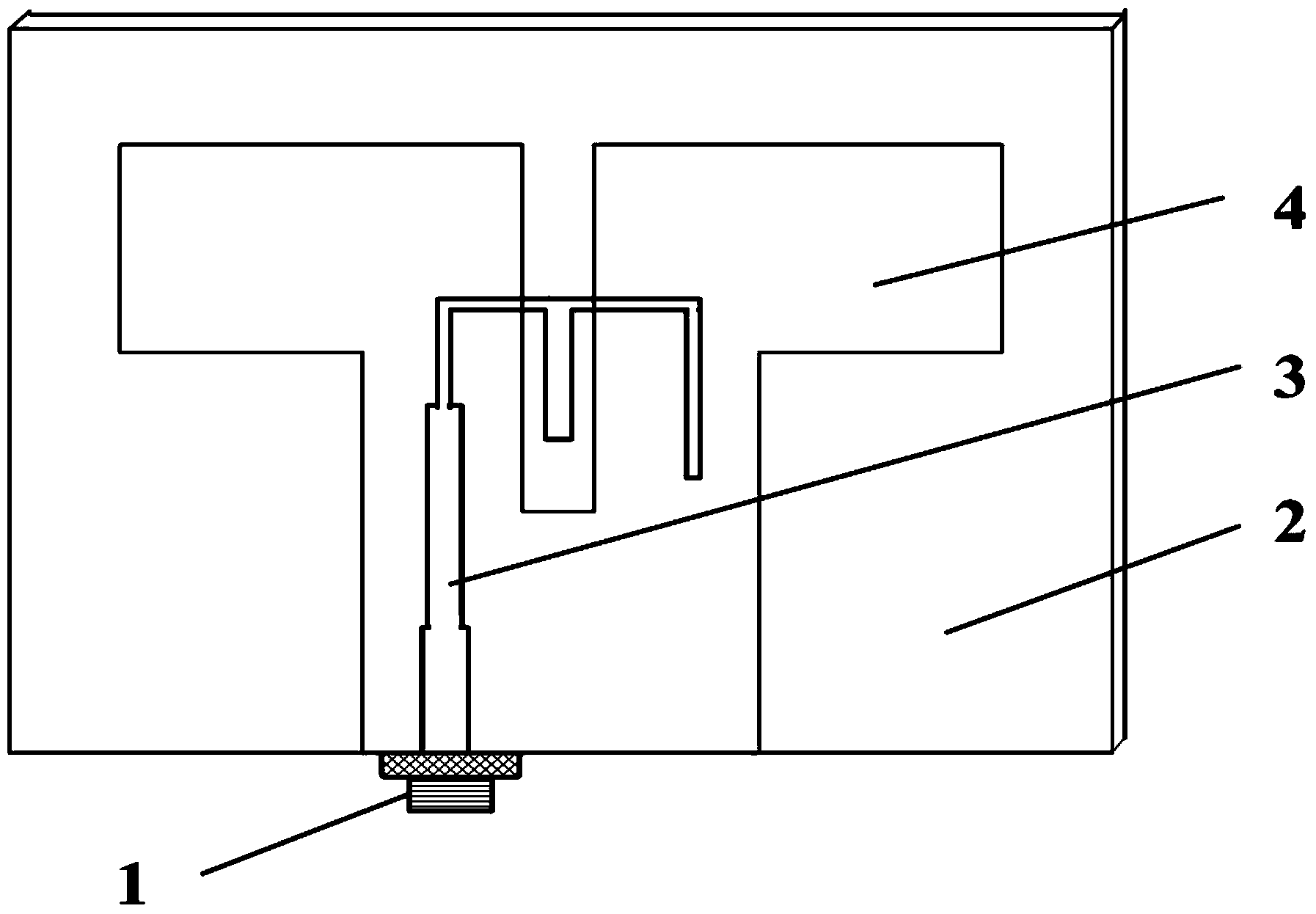
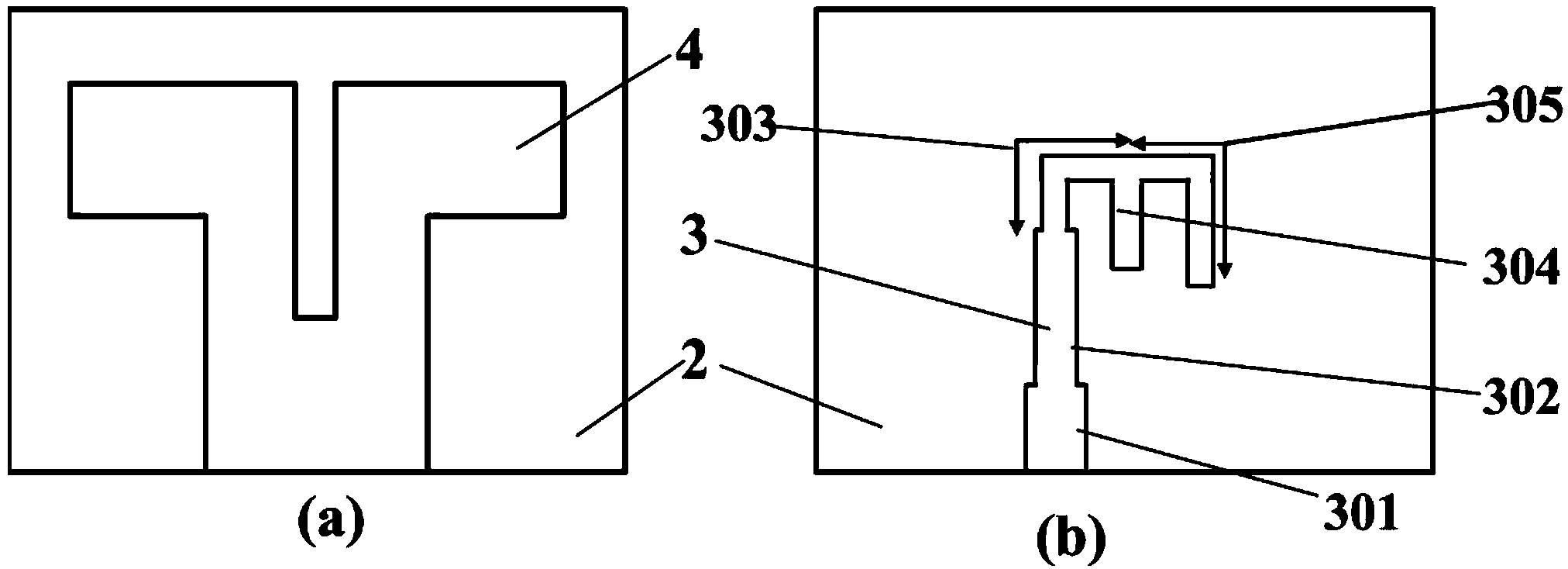
[0040] The dielectric board 2 is an FR4 dielectric board with a dielectric constant of 4.4 and a thickness of 1.5 mm, with a length of 82 mm and a width of 62 mm. The length of the upper end of the radiation unit 4 is 72 mm, about half the wavelength of the center frequency of 2.3 GHz, and the width is 23 mm. The height of the radiation unit 4 is 55 mm, and the width of the lower end is 30 mm. In the middle of the radiation unit 4, there is a slot with a width of 5 mm and a length of 32 mm.

[0041] The total height of the microstrip feed integrated balun 3 on the opposite side of the dielectric board 2 is 39.8 mm. The microstrip line 301 with a characteristic impedance of 50 ohms has a length of 11 mm and a width of 2.8 mm. The first-stage impedance transformation section 302 is 20 mm long and 2 mm wide. The width of the second fold line impedance transformation section 303 is 0.8mm, the length of the vertical section i...

Embodiment 2

[0045] Embodiment 2, double-layer structure plus reflector antenna

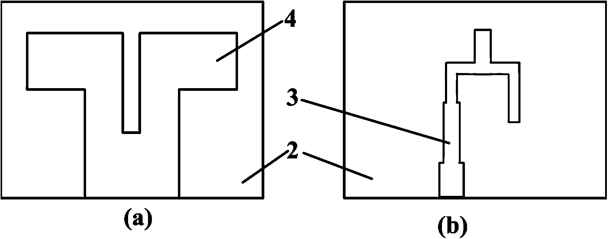
[0046] refer to Figure 4 , according to the antenna with the single-layer structure above, a double-layer dielectric board structure antenna is designed. Such as Figure 4 , further includes a metal reflector 5, the dielectric plate 2 is two pieces, the two dielectric plates 2 are stacked together to form a double-layer dielectric plate, the double-layer dielectric plate is vertically arranged on the metal reflector 5, the double-layer dielectric The aforementioned radiation unit 4 is printed on both outer surfaces of the board, and the aforementioned stripline integrated feed balun 3 is printed on the middle interlayer of the double-layer dielectric board.

[0047] Dielectric plate 2 selects the FR4 medium plate that dielectric constant is 4.4, thickness is 1.5mm for use, and the metal reflector 5 top that adds is long 92mm, and height is 64mm, medium plate; Metal reflector 5 lower end dielectric plates a...


PUM

PropertyMeasurementUnit
Thicknessaaaaaaaaaa
Thicknessaaaaaaaaaa

Abstract

The invention discloses a novel broadband printed dipole antenna with a branch wire integrated with a feed balun. The novel broadband printed dipole antenna comprises an SMA (Shape Memory Alloy) joint, a dielectric-slab, a radiating element and a microstrip line feed integrated balun, wherein the radiating element is provided with a slotting seam; dual radiation arms are formed on both sides of the slotting seam; the microstrip line feed integrated balun is provided with a branch wire; the branch wire is equivalent to a series resistor, and is used for improving the matched impedance. According to the novel broadband printed dipole antenna, the VSWR (Voltage Standing Wave Ratio) is less than or equal to 1.5, and the relative bandwidth is up to 58.7 percent (1.65-3.0GHz); compared with other bandwidth extension technologies (such as a parasitic patch increasing technology), the novel broadband printed dipole antenna has the advantages that design is made on the basis of not changing the original size of the antenna, so that the bandwidth of the antenna is improved, other performance of the antenna (such as gain and cross polarization level) is not influenced, and the occupied space is reduced; the novel broadband printed dipole antenna has the advantages of simple structure, convenience, practicability, wide adaptability and the like.

Description

technical field [0001] The invention relates to the technical field of antenna engineering, in particular to a novel wideband printed dipole antenna with a branch line integrated feed balun, which is used for antennas of mobile communication equipment or elements of array antennas. Background technique [0002] With the rapid development of radio communication technologies, such as 2G GSM1800 and GSM1900, 3G (CDAM-2000, WCDMA and TD-SCDMA) and LTE, the communication frequency bands of these communication systems are mainly 1.7-2.8 GHz. The dipole structure antenna is widely used in antenna engineering technology. Its structure is simple and easy to implement, and it can work alone as an antenna, or as an antenna element of an antenna array. The printed dipole antenna fed by the microstrip balun structure is widely used in various wireless communication systems because it can provide a large bandwidth, and has the advantages of small size, light weight, low cost, easy integr...

Claims


Application Information

Patent Timeline
IPC IPC(8): H01Q1/38H01Q9/06H01Q9/28H01Q1/36H01Q13/10
Inventor 王灿葛悦禾
Owner HUAQIAO UNIVERSITY
Why Eureka
Try Eureka