MOCVD reaction room used for growing graphene

A reaction chamber and graphene technology, applied in the field of microelectronics, can solve the problems of poor uniformity of graphene materials, complex procedures, poor temperature uniformity, etc., and achieve the effects of improving crystal quality and effective area, improving preparation efficiency, and improving uniformity.

Active Publication Date: 2014-02-19
XIDIAN UNIV
View PDF2 Cites 16 Cited by
  • Summary
  • Abstract
  • Description
  • Claims
  • Application Information

AI Technical Summary

Problems solved by technology

The former is based on transition group metal catalysis and metal-carbon solid solution-precipitation-reconstruction mechanism, and is not limited by the substrate area, and can prepare ultra-large-area graphene materials. The transfer process transfers graphene to a suitable substrate, and impurities and defects are introduced during the transfer process, making it difficult to ensure cleanliness; the latter is based on the mechanism of SiC substrate decomposition-Si evaporation-C reconstruction, which can obtain crystallization properties Better graphene, but limited by the size of the SiC substrate, the obtained graphene area is small, harsh process conditions and expensive equipment increase the cost of graphene growth, and this method is not compatible with the existing Si process
[0005] The use of MOCVD technology can effectively overcome the shortcomings of the above-mentioned epitaxial technology, but it is very difficult to directly use the current MOCVD equipment to grow graphene materials. The main reasons are: (1) The current MOCVD equipment is mainly used to grow compound semiconductors, Such as GaAs, GaN, etc., but they are not suitable for the growth of metal thin films in terms of pressure control, reaction chamber structure, gas source transportation, etc.; (2) One of the core processes of graphene growth is the C atom precipitation process, which is A cooling process, the current MOCVD equipment is designed for a constant temperature process, it is almost impossible to control the cooling process, and the temperature uniformity during the cooling process is very poor, which will lead to poor uniformity of the graphene material

Method used


Image

  • MOCVD reaction room used for growing graphene
  • MOCVD reaction room used for growing graphene
  • MOCVD reaction room used for growing graphene

Examples


Embodiment 1

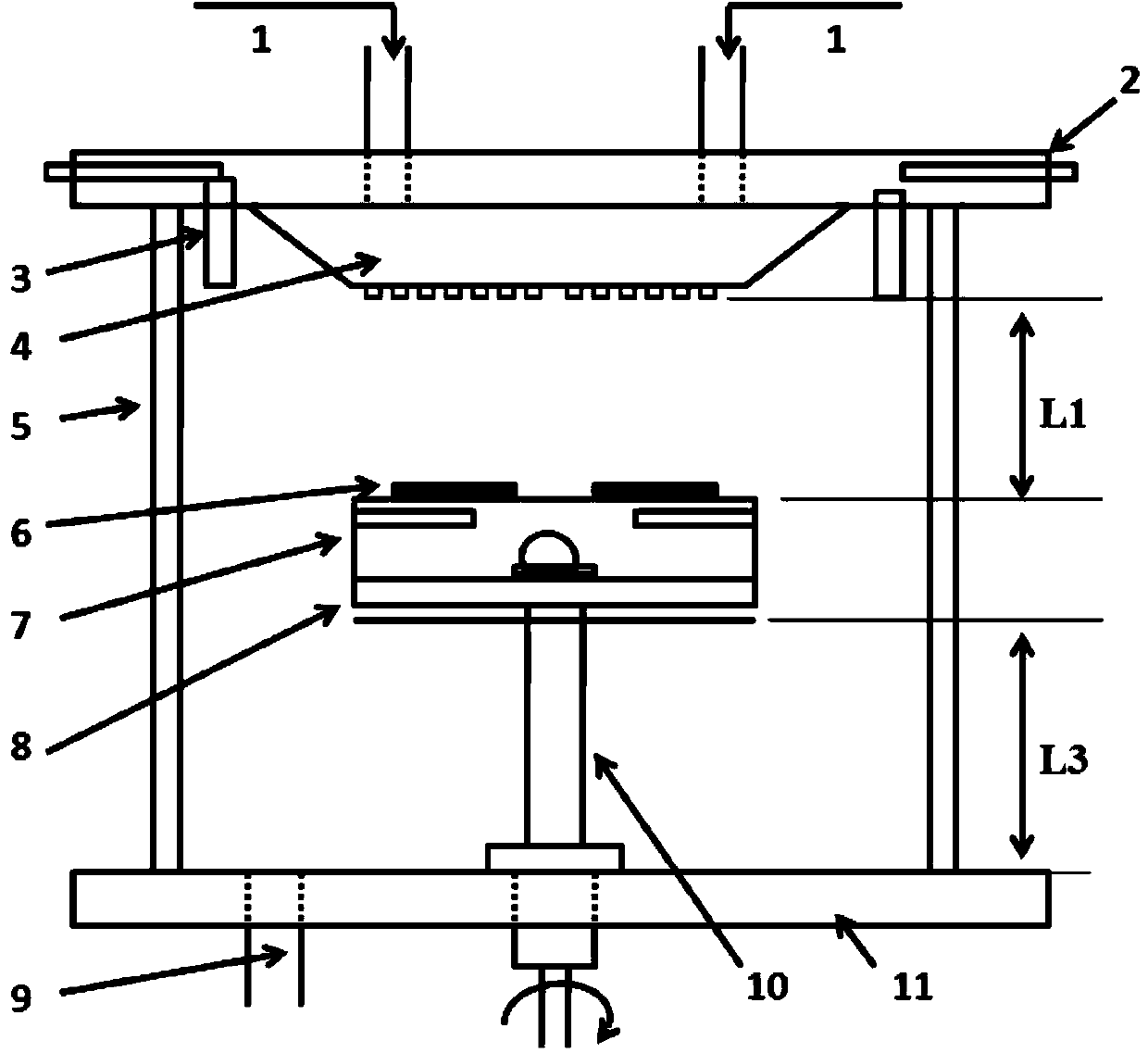
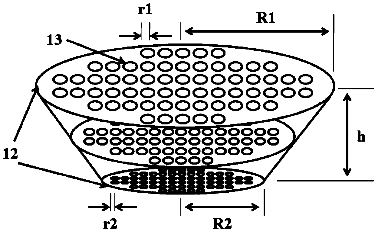
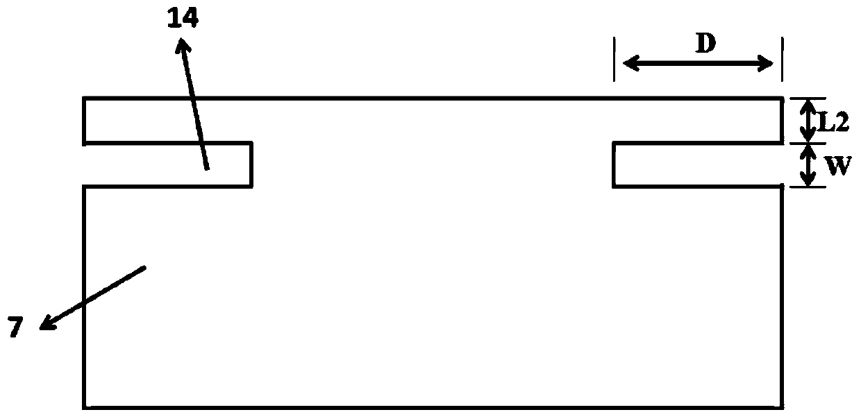
[0033] The radius R1 of the upper surface of the sprinkler 12 is 6 cm, the radius R2 of the lower surface is 3 cm, the height h of the sprinkler 4 is 2 cm, the number of nozzles N is 20, the radius r1 of the top nozzle is 2 mm, and the radius r2 of the bottom nozzle is 1 mm The depth D of the groove 14 is 10mm, the height W is 1mm, the distance L2 between the groove and the base surface is 2mm; the distance L1 between the shower head 4 and the graphite base 7 is 10cm, and the graphite base 7 and the exhaust port 9 The distance L3 is 10cm; the revolution speed of the graphite base 7 is 100r / min, and the rotation speed is 100r / min; the purge gas is Ar.

Embodiment 2

[0035]The radius R1 of the upper surface of the sprinkler 12 is 7cm, the radius R2 of the lower surface is 3.5cm, the height h of the sprinkler 4 is 2.5cm, the number of nozzles N is 30, the radius r1 of the top nozzle is 3mm, and the radius r2 of the bottom nozzle 1.5mm; the depth D of the groove 14 is 15mm, the height W is 2mm, the distance L2 between the groove and the base surface is 4mm; the distance L1 between the shower head 4 and the graphite base 7 is 12cm, the graphite base 7 and the row The distance L3 of the gas port 9 is 12cm; the revolution speed of the graphite base 7 is 200r / min, and the rotation speed is 120r / min; the purge gas is H 2 .

Embodiment 3

[0037] The radius R1 of the upper surface of the sprinkler 12 is 10 cm, the radius R2 of the lower surface is 5 cm, the height h of the sprinkler 4 is 4 cm, the number of nozzles N is 60, the radius r1 of the top nozzle is 5 mm, and the radius r2 of the bottom nozzle is 2.5 mm; the depth D of the groove 14 is 25mm, the height W is 4mm, the distance L2 between the groove and the base surface is 8mm; the distance L1 between the shower head 4 and the graphite base 7 is 15cm, and the graphite base 7 and the exhaust port The distance L3 of 9 is 15cm; the revolution speed of the graphite base 7 is 500r / min, and the rotation speed is 300r / min; the purge gas is N 2 .

[0038] During work, at first the semiconductor insulating substrate 6 is placed on the top of the graphite base 7, then the transition metal organic source is passed into the reaction chamber from the source inlet 1, and the purge gas is passed into the reaction chamber from the purge air flow device, by changing The c...


PUM

PropertyMeasurementUnit
depthaaaaaaaaaa
heightaaaaaaaaaa

Abstract

The invention discloses an MOCVD reaction room used for growing grapheme. The MOCVD reaction room mainly solves the problems that according to an existing epitaxy technique, the preparing efficiency is low, the crystalline quality is poor and the effective area is small. The MOCVD reaction room comprises source inlets (1), a top plate (2), purging air flow (3), an inverted tower-shaped spray head (4), quartz tubes (5), a groove graphite base (7), a resistance heating device (8), an air exhaust opening (9), a rotary support (10) and a supporting plate (11). The quartz tubes (5) are fixed to the upper portion of the supporting plate (11), the top plate (2) is located on the upper portions of the quartz tubes (5), the rotary support (10) is located between the quartz tubes (5) and is fixed to the supporting plate (11), the spray head (4) is fixed to the lower portion of the top plate (2), the purging air flow (3) is evenly distributed in a whole circular cavity between the quartz tubes (5) and the spray head (4), the heating device (8) is fixed to the upper portion of the support (10), and the groove graphite base (7) is located on the upper portion of the heating device (8) and right faces the lower surface of the spray head (4). The MOCVD reaction room is simple in structure, improves evenness of the air flow and the temperature in the reaction cavity and can be used for growing of high-quality and large-size grapheme.

Description

technical field [0001] The invention belongs to the field of microelectronic technology, and relates to key equipment for semiconductor material preparation, in particular to a reaction chamber based on metal-organic source chemical vapor deposition (MOCVD), which can be used for in-situ growth of wafer-level, high-quality graphene materials. Background technique [0002] With the development of integrated circuits, the critical dimensions of silicon (Si)-based devices have reached the theoretical and technical limits, and quantum effects have become the main mechanism. Traditional Si-based devices based on the diffusion-drift theory are limited by both physics and technology. Continue to undertake the important task of continuing Moore's Law. Therefore, it is necessary to find a new generation of basic semiconductor materials and develop new theories and device models to meet the needs of the continued development of integrated circuits. [0003] Graphene material is a carb...

Claims


Application Information

Patent Timeline
Patent Type & Authority Applications(China)
IPC IPC(8): C30B25/08C30B25/02
Inventor 王东韩砀宁静柴正闫景东张进成郝跃
Owner XIDIAN UNIV
Why Eureka
Try Eureka