
Tire treatment system

A technology for processing systems and tires, which is applied in special forms of dry distillation, preparation of liquid hydrocarbon mixtures, and coke ovens. The effect of secondary cracking and reducing operating costs

Active Publication Date: 2014-03-26
北京节净环保科技有限公司
View PDF12 Cites 14 Cited by
  • Summary
  • Abstract
  • Description
  • Claims
  • Application Information

AI Technical Summary

Problems solved by technology

[0004] At present, the pyrolysis gas produced after pyrolysis of waste tires will result in the generation of secondary reactions, resulting in poor quality pyrolysis oil obtained from tire pyrolysis and increased asphaltene content.
And because oil and gas are cooled by water in the prior art, the oil-water mixture obtained needs to be further separated from oil and water. The complicated process increases the cost of pyrolysis, and the infiltration of water greatly reduces the quality of oil.
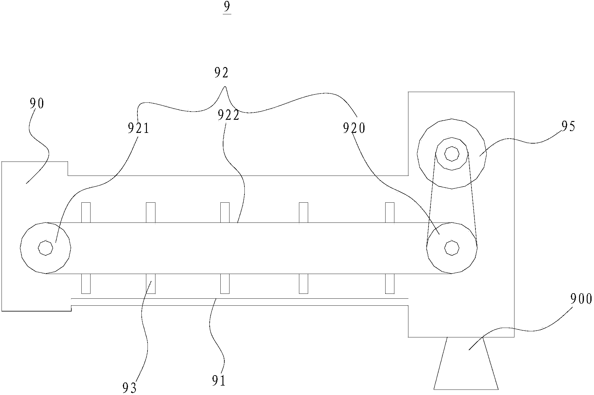
[0005] Since the solid product after pyrolysis of waste tires contains steel wire components and has a large friction coefficient, the iron wire cannot be discharged smoothly when using the discharge screw device of the prior art, that is, the iron wire in the solid product will accumulate in the discharge screw device , easy to form iron balls, resulting in difficulty in discharging, and in serious cases, the screw in the discharging screw device will be stuck, and the carbon black ground by the discharging screw device is fine and light, and it is easy to disperse into the atmosphere and cause an explosion accident

Method used


Image

  • Tire treatment system
  • Tire treatment system
  • Tire treatment system

Examples


Embodiment Construction

[0038] Embodiments of the present invention are described in detail below, examples of which are shown in the drawings, wherein the same or similar reference numerals designate the same or similar elements or elements having the same or similar functions throughout. The embodiments described below by referring to the figures are exemplary only for explaining the present invention and should not be construed as limiting the present invention.

[0039]In describing the present invention, it should be understood that the terms "center", "longitudinal", "transverse", "upper", "lower", "front", "rear", "left", "right", " The orientations or positional relationships indicated by "vertical", "horizontal", "top", "bottom", "inner", "outer", etc. are based on the orientation or positional relationships shown in the drawings, and are only for the convenience of describing the present invention and simplifying Describes, but does not indicate or imply that the device or element referred ...


PUM


Abstract

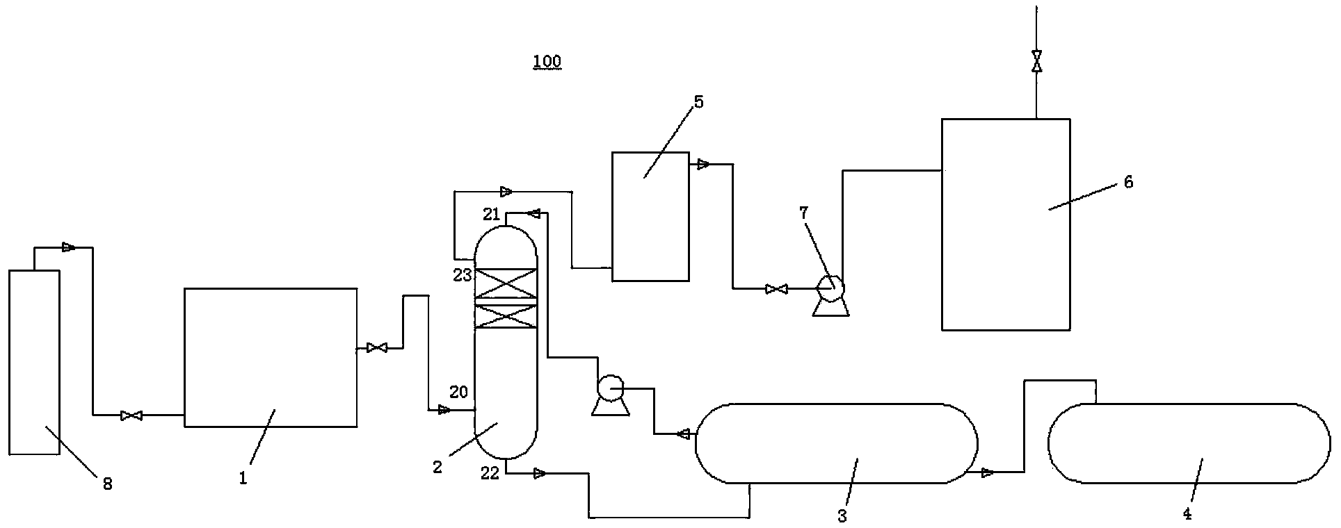
The invention discloses a tire treatment system. The tire treatment system comprises a pretreatment device, a revolving bed pyrolyzing furnace, a heat accumulating type fuel gas radiating pipe burner, a direct cooling tower, an oil cooler, an oil storage tank, a purifier, and a gas storage tank, wherein the pretreatment device treats a tire so as to form a pyrolyzing raw material. The revolving bed pyrolyzing furnace receives the pyrolyzing raw material, and a plurality of gas outlets are formed in the side wall of the revolving bed pyrolyzing furnace. The heat accumulating type fuel gas radiating pipe burner heats the pyrolyzing raw material, and a plurality of gas outlets are located below the heat accumulating type fuel gas radiating pipe burner in vertical direction. The direct cooling tower receives an oil-gas product and separates oil from gas. The oil cooler receives and cools the separated pyrolyzing oil, and the cooled pyrolyzing oil is introduced into the direct cooling tower. The oil storage tank and the oil cooler are communicated. The purifier receives the separated pyrolyzing gas. The gas storage tank and the purifier are communicated, and the gas storage tank provides a gas source for the heat accumulating type fuel gas radiating pipe burner. The tire treatment system, pyrolyzing oil is high in yield and good in quality, and the operating cost is low.

Description

technical field [0001] The invention relates to the field of garbage disposal, in particular to a tire disposal system. Background technique [0002] Waste tires are difficult to biodegrade. Long-term storage in the open air not only takes up a lot of land, but also produces toxic and harmful gases, seriously polluting the environment. At present, the comprehensive utilization methods of waste tires mainly include retreading, reclaimed rubber, rubber powder, thermal energy utilization and pyrolysis, among which pyrolysis has attracted widespread attention due to its high resource recovery rate and low secondary pollution. [0003] Pyrolysis technology is to heat organic matter to 500-1000°C in an oxygen-free or oxygen-deficient state, so that the organic matter in solid waste is converted into stored energy mainly including gas, fuel oil and pyrolytic charcoal. Due to the anoxic decomposition, the reducing atmosphere can reduce the secondary pollution of the environment by ...

Claims


Application Information

Patent Timeline
IPC IPC(8): C10B53/07C10G1/10B09B3/00
CPCY02P20/143
Inventor 吴道洪吴小飞肖磊
Owner 北京节净环保科技有限公司
Learn More