Vascular restraint device

A blood vessel and rigid frame technology, applied in the field of medical devices, can solve problems such as false lumen tumor-like expansion, damage to the vascular intima, and blood cell destruction, and achieve the effects of preventing expansion, reducing the thrombosis rate, and protecting the vascular intima

Active Publication Date: 2016-05-18
蚌埠中知知识产权运营有限公司
View PDF6 Cites 0 Cited by
  • Summary
  • Abstract
  • Description
  • Claims
  • Application Information

AI Technical Summary

Problems solved by technology

Once the proximal end of the stent-graft is in contact with the blood vessel, the cavity will be subjected to high pressure under the impact of blood flow, so that the blood flow runs through the entire gap, forming an endoleak. After the endoleak occurs, the false lumen is difficult to Complete thrombosis can lead to complications such as false lumen tumor-like expansion and dissection rupture, and ultimately treatment failure; 2. The stent-graft causes a new breach: there are many reasons for this complication, among which the contact area between the stent-graft and the blood flow Large, under the impact of large blood flow, in order to stabilize the stent, the proximal stent needs to have a large tension to compress the aorta to avoid displacement. The role of the membrane in maintaining the stability of the blood coagulation system is crucial. At present, artificial vascular replacement, endoluminal stent graft isolation and other treatments have seriously damaged the local vascular intima, resulting in blood cell destruction and thrombus formation; 3. Thrombosis: covered stent graft The area in contact with the blood flow is large, and it is difficult for the vascular endothelium to cover the stent graft, so there is still a high rate of thrombosis. 4. Paraplegia and other important organ ischemia is caused by the stent graft blocking the blood flow of important vascular branches

Method used


Image

  • Vascular restraint device
  • Vascular restraint device

Examples


Embodiment Construction

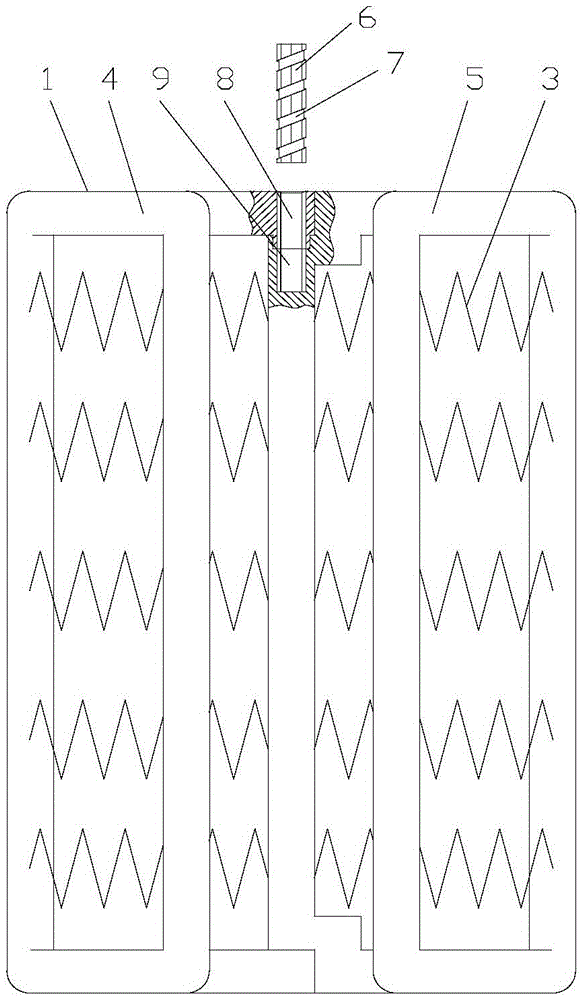
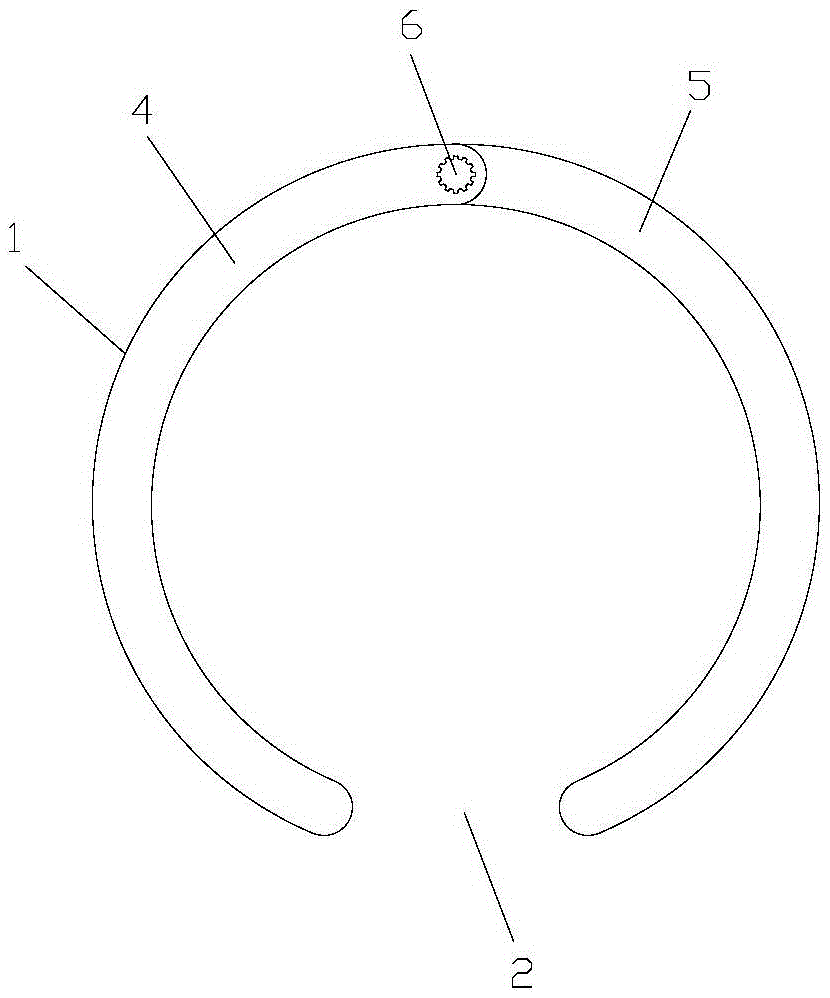
[0015] figure 1 is the front view of the present invention; figure 2 for figure 1 As shown in the figure: the vascular binding device of this embodiment includes a hollow cylindrical rigid frame 1; one radial side of the rigid frame 1 is cut off to form a gap 2 with a certain width, through which the The rigid frame 1 is set on the outside of the blood vessel, and the inner diameter of the rigid frame 1 is slightly smaller than the outer diameter of the corresponding vascular lesion, so that the rigid frame 1 can be fastened to the outer wall of the blood vessel and fixed. For the part with branch blood vessels, the gap 2 faces the side where the branch blood vessels are located It can give way to the branch blood vessels, and if the diameter of the branch blood vessels is large, it can also set up a way groove at the edge of the gap 2; it also includes an elastic body 3 fixed between the frames of the rigid frame 1 to form a half-ring structure, The elastic body 3 can adap...


PUM


Abstract

The invention discloses a blood vessel constraining device which comprises a hollow cylindrical rigid frame. One radial side of the rigid frame is broken. The device further comprises an elastic body which is fixed between borders of the rigid frame and forms a semi-ring sleeve structure. The blood vessel constraining device can improve the tension stress performance of a vascular wall, angiectasis and angiorrhexis can be prevented, direct contact of instruments and blood vessel endothelium and blood is avoided, the blood and the blood vessel endothelium are protected, extracorporeal circulation is avoided, operation is easy, time is short, trauma is small, treatment effect can be greatly improved, meanwhile, a bare stent placed in a lumen can be combined for treating artery dissection, the inner portion and the outer portion of the vascular wall are clamped tightly, the mechanical strength of the vascular wall is improved, damage on an aorta intima is lowered, forming rate of inner membrane crevasses is lowered, inner leakage is avoided, the function of vessel inner membrane protecting is achieved, thrombus-causing rate can be lowered, the bare stent has no influence on blood supply of an aorta branch vessel, the occurrence rate of paraplegia is lowered, the implanting range is wide, a false lumen is fully closed, and the shortcoming that an existing later-period false lumen is not completely closed continuously is overcome.

Description

technical field [0001] The invention relates to a medical device, in particular to a blood vessel binding device. Background technique [0002] Aneurysm is a very dangerous vascular disease clinically. Once an aneurysm is found, it needs to be treated as soon as possible. The current treatment measures are mainly divided into: 1. Surgical vascular replacement. The curative effect is relatively definite, but most of these patients are elderly, the surgical trauma is large, most patients need extracorporeal circulation, the perioperative mortality rate is high, and complications such as postoperative thrombosis, important vascular branch stenosis, and anastomotic expansion are relatively common. 2. Minimally invasive interventional therapy technology using the principle of intracavitary isolation. It uses a set of delivery system with a small diameter to deliver the compressed stent graft with support to the position of the vascular lesion. After accurate positioning, the It ...

Claims


Application Information

Patent Timeline
Patent Type & Authority Patents(China)
IPC IPC(8): A61B17/12
CPCA61B17/12009
Inventor 李宝童杨丽莎
Owner 蚌埠中知知识产权运营有限公司
Why Eureka
Try Eureka