Ultralow-emission power generation system using low-calorific-value fuel for combustion

A power generation system, low calorific value technology, applied in the direction of burning fuel in molten state, combustion method, combustion type, etc., can solve the problems of difficult dust emission, low combustion efficiency, low boiler efficiency, etc., to avoid low-temperature corrosion and dust accumulation, Optimize the working environment and improve the effect of dust removal efficiency

Active Publication Date: 2014-07-02
HUANENG CLEAN ENERGY RES INST
View PDF11 Cites 9 Cited by
  • Summary
  • Abstract
  • Description
  • Claims
  • Application Information

AI Technical Summary

Problems solved by technology

[0005] 2) Adding limestone can achieve desulfurization in furnace combustion, and the desulfurization efficiency can reach 90%, but the Ca / S molar ratio is high (usually 3 or even higher), and the utilization rate of limestone is low (less than 40%);
[0006] 3) The low-temperature combustion method is adopted, the combustion efficiency is low, and the boiler efficiency is low;
[0007] 4) The low calorific value fuel has high ash content, which is affected by the low efficiency of the dust collector, and the dust emission concentration is high;
[0008] 5) After the desulfurization in the furnace is adopted, a large amount of CaSO is mixed in the ash 3 , CaO, etc., coupled with the high carbon content of fly ash, it is not easy to comprehensively utilize the ash
Although the desulfurization efficiency of conventional circulating fluidized bed boilers can reach 90%, SO 2 The emission concentration is lower than 100mg / m 3 Difficult to achieve, NO controlled by combustion x The emission concentration is lower than 100mg / m 3 It is also difficult to achieve. The conventional dust removal method should make the dust emission reach 30mg / m 3 even lower is difficult
Therefore, combined with the current environmental protection situation, conventional circulating fluidized bed boilers cannot meet the requirements of large-scale clean utilization of low calorific value fuels

Method used


Image

  • Ultralow-emission power generation system using low-calorific-value fuel for combustion
  • Ultralow-emission power generation system using low-calorific-value fuel for combustion

Examples


Embodiment 1

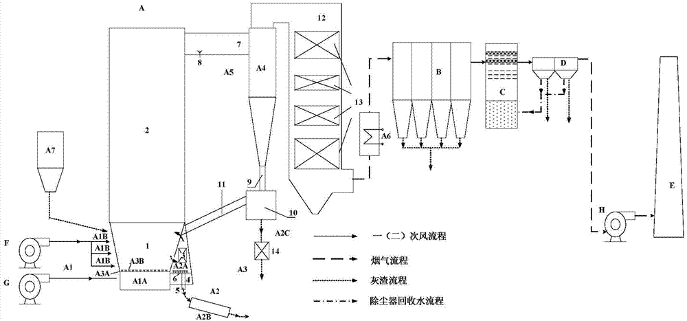
[0058] The attached picture shows a 300MW high-efficiency ultra-low-emission power generation system using low-calorific-value fuels. The boiler is a single-chamber structure, and there is only one set of low-resistance air distribution device A3. The boiler fuel is gangue with low calorific value of 8360kJ / kg (2000kCal / kg) as received. The gangue is sent to the high-temperature circulating fluidized bed boiler A for combustion. The combustion temperature is 1000°C. The air required for combustion is supplied by the controllable multi-stage air supply system A1. The ratio of primary air: secondary air is 4:6.

[0059] In this application example, the high-temperature flue gas generated by the high-temperature circulating fluidized bed boiler A is lowered to 90°C through the powerful flue gas cooler A6, and then enters the low-temperature dust collector B to remove most of the fly ash in the flue gas and send it to the wet process Flue gas desulfurization system C, the flue gas...

Embodiment 2

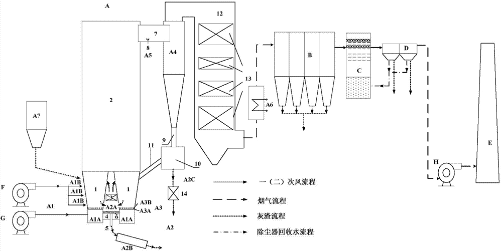
[0065] The attached picture shows a 330MW high-efficiency ultra-low emission power generation system using low calorific value fuel. The boiler has a double air distribution plate structure and is equipped with 2 sets of low resistance air distribution devices A3. The boiler fuel is gangue with low calorific value of 10450kJ / kg (2500kCal / kg) as received. The gangue is sent to the high-temperature circulating fluidized bed boiler A for combustion, the combustion temperature is 980°C, and the air required for combustion is supplied by the controllable multi-stage air supply system A1.

[0066] In this application example, the high-temperature flue gas generated by the high-temperature circulating fluidized bed boiler A is lowered to 80°C through the powerful flue gas cooler A6, and then enters the low-temperature dust collector B to remove most of the fly ash in the flue gas and send it to the wet process Flue gas desulfurization system C, deeply desulfurized SO 2 The concentra...


PUM

PropertyMeasurementUnit
separationaaaaaaaaaa

Abstract

The invention discloses an ultralow-emission power generation system using low-calorific-value fuel for combustion. The ultralow-emission power generation system comprises a high temperature circulating fluidized bed boiler, a low temperature dust remover, a wet-process smoke desulphurization system and a wet type electric dust remover, wherein the high temperature circulating fluidized bed boiler comprises a controllable multi-stage air supply system, an ash staging cooling and discharging system, a low resistance air distribution device, a highly efficient cyclone separator, a deep denitration system and a strong smoke cooler and is small in N2O emission amount, and porous ashes are used for adsorbing SO3 and heavy metals; the ash concentration in the boiler and material grain size distribution can be adjusted through the ash staging cooling and discharging system when the low-calorific-value fuel for combustion is combusted so as to optimize combustion, heat transmission and flowing; the ultralow emission of NOx is realized through the controllable multi-stage air supply system and the deep denitration system; the ultralow emission of SO2 is realized by combining the wet-process smoke desulphurization system and calcium-injection desulfurization in the boiler; the ultralow emission of dust is realized through the lower temperature dust remover, the wet-process smoke desulphurization system and the wet type electric dust remover. According to the ultralow-emission generation system, the emission standards of thermal power plants and natural gas turbine generator units in key areas, the cost of pollutant removal is low and the environmental benefit is remarkable.

Description

technical field [0001] The invention relates to the technical field of low-calorific-value fuel combustion, in particular to an ultra-low-emission power generation system for low-calorific-value fuel. Background technique [0002] my country is the world's major coal producer and consumer, and also a country that uses coal as its primary energy source. With the production and washing of coal, a large amount of low calorific value fuels (including gangue, washed medium coal, coal slime, etc.) are produced. If not utilized, a large amount of land will be occupied and the environment will be polluted. Due to the low calorific value of fuel, the converted sulfur content and converted ash content are very high, so it is difficult to burn efficiently, and the amount of pollutant emissions is also large. [0003] Since pulverized coal boilers have high requirements for fuel and cannot use low calorific value fuels, conventional circulating fluidized bed boilers are widely used in ...

Claims


Application Information

Patent Timeline
Patent Type & Authority Applications(China)
IPC IPC(8): F23C10/00F23C10/18F23C10/20B01D50/00B01D53/79B01D53/60
CPCY02A50/20Y02A50/2351
Inventor 蒋敏华肖平黄中徐正泉江建忠
Owner HUANENG CLEAN ENERGY RES INST
Why Eureka
Try Eureka