Conductive paste and method for producing conductive pattern
A conductive paste, conductive technology, applied in conductive materials dispersed in non-conductive inorganic materials, printed circuit manufacturing, cable/conductor manufacturing, etc. and other problems to achieve the effect of good connection reliability
- Summary
- Abstract
- Description
- Claims
- Application Information
AI Technical Summary
Problems solved by technology
Method used
Image
Examples
Embodiment
[0060] Examples of the present invention will be described below, but the present invention is not limited to these Examples. Materials and evaluation methods used in Examples and Comparative Examples are as follows.
[0061]
[0062] Regarding the aspect ratio of the composite particles (A), the aspect ratios of 100 particles were obtained from the SEM or TEM images, and the average value was taken.
[0063]
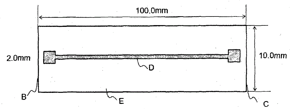
[0064] Coat the conductive paste on the PET film in such a way that the dry thickness reaches 10 μm, and dry it in a drying oven at 90°C for 5 minutes. ) as a unit, exposed and developed through a photomask having a light-transmitting pattern having 9 types of units with different L / S values, and then cured at 130°C for 1 hour to obtain Get a conductive pattern. The L / S value of each unit is set to 500 / 500, 250 / 250, 100 / 100, 50 / 50, 40 / 40, 30 / 30, 25 / 25, 20 / 20, 15 / 15 (indicating the line width (μm) / interval (μm)). The pattern was observed with an optical microscop...
Synthetic example 1
[0082] (Synthesis Example 1) Compound B-1 with an acid value in the range of 30 to 250 mgKOH / g
[0083] Copolymer of ethyl acrylate (EA) / 2-ethylhexyl methacrylate (2-EHMA) / styrene (St) / acrylic acid (AA) (copolymerization ratio: 20 parts by weight / 40 parts by weight / 20 The substance obtained by addition reaction of 5 parts by weight of glycidyl methacrylate (GMA) in parts by weight / 15 parts by weight)
[0084] 150 g of diethylene glycol monoethyl ether acetate was put into the reaction container of nitrogen atmosphere, and it heated up to 80 degreeC using an oil bath. 20 g of ethyl acrylate, 40 g of 2-ethylhexyl methacrylate, 20 g of styrene, 15 g of acrylic acid, 0.8 g of 2,2'-azobisisobutyronitrile, and diethylene glycol were added dropwise thereto over 1 hour. A mixture of monoethyl ether acetate 10 g. After completion of the dropwise addition, polymerization reaction was further performed for 6 hours. Then, 1 g of hydroquinone monomethyl ether was added to stop the polym...
Synthetic example 2
[0085] (Synthesis Example 2) Compound B-2 with an acid value of 30 to 250 mgKOH / g
[0086] Copolymer of ethylene oxide-modified bisphenol A diacrylate FA-324A (product name, manufactured by Hitachi Chemical Industry Co., Ltd.) / EA / AA (copolymerization ratio: 50 parts by weight / 10 parts by weight / 15 parts by weight) Product obtained by addition reaction with 5 parts by weight of glycidyl methacrylate (GMA)
[0087]150 g of diethylene glycol monoethyl ether acetate was put into the reaction container of nitrogen atmosphere, and it heated up to 80 degreeC using an oil bath. It took 1 hour to dropwise add 50 g of ethylene oxide modified bisphenol A diacrylate FA-324A, 20 g of ethyl acrylate, 15 g of acrylic acid, 0.8 g of 2,2'-azobisisobutyronitrile and diethylene glycol Alcohol monoethyl ether acetate 10g mixture. After the dropwise addition was completed, polymerization was carried out for a further 6 hours. Then, 1 g of hydroquinone monomethyl ether was added to stop the poly...
PUM
| Property | Measurement | Unit |
|---|---|---|
| Acid value | aaaaa | aaaaa |
| Glass transition temperature | aaaaa | aaaaa |
| Line width | aaaaa | aaaaa |
Abstract
Description
Claims
Application Information
 - R&D
- Intellectual Property
- Life Sciences
- Materials
- Tech Scout
- Unparalleled Data Quality
- Higher Quality Content
- 60% Fewer Hallucinations
Browse by: Latest US Patents, China's latest patents, Technical Efficacy Thesaurus, Application Domain, Technology Topic, Popular Technical Reports.
© 2025 PatSnap. All rights reserved.Legal|Privacy policy|Modern Slavery Act Transparency Statement|Sitemap|About US| Contact US: help@patsnap.com


