

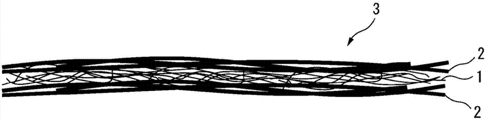
Separator
A technology for separators and non-woven fabrics, which is applied in the direction of electrical components, structural parts, battery pack components, etc., and can solve the problems of low uniformity of spunbonded non-woven fabric layers, reduced electrolyte mobility, and electrolyte retention.
- Summary
- Abstract
- Description
- Claims
- Application Information
AI Technical Summary
Problems solved by technology
Method used
Image

Examples
Embodiment 1~11
[0105] Laminated nonwoven fabrics of Examples 1 to 11 were produced by the following method, and performance evaluation was implemented.
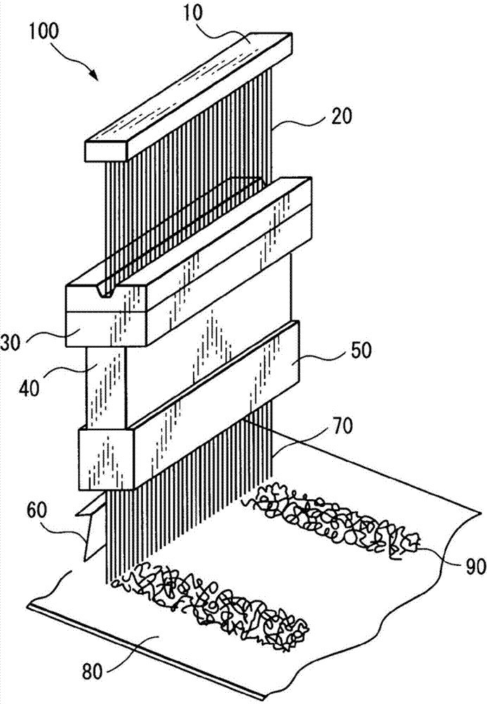
[0106] In order to obtain the ultrafine fiber web for the ultrafine fiber nonwoven fabric layer (I layer), a solution of PET (having a melt viscosity measured at a temperature of 35° C. using OCP as a solvent: ηsp / c=0.50), At spinning temperature 300°C, heating air 1000Nm 3 Under the condition of / hr / m, it is extruded towards the moving catch net and spun by melt blowing method. At this time, the distance from the melt-blowing nozzle to the microfiber web was 100 mm, the suction force of the collecting surface directly below the melt-blowing nozzle was 0.2 kPa, and the wind speed was 7 m / sec. Adjustment of the fiber diameter and degree of crystallization was performed by adjusting the amount of heated air.
[0107] Next, in order to obtain a nonwoven fabric layer (layer II) made of thermoplastic resin fibers, a solution of general-purpose...
Embodiment 12
[0110] As the non-woven fabric layer (I layer), in the same manner as in Example 1, a melt-blown fiber web that becomes the non-woven fabric layer (I) layer is made; as the non-woven fabric layer (II layer), a fiber diameter of 18 μm and a fiber length of 5mm short fiber of co-PET / PET sheath core structure. Concretely, capture by the shoveling method so that the net becomes 30g / m 2 , after dehydration and drying, the fibers were fused with a hot air method (180° C., 5 m / min) to obtain a nonwoven fabric layer (layer I) / short fiber web (layer II). Furthermore, the nonwoven fabric layer (1 layer) produced similarly to Example 1 was laminated|stacked on the web obtained above, and the laminated web which consists of 3 layers was obtained. The obtained laminated web was thermally bonded with a flat roll and a calender roll to obtain a laminated nonwoven fabric. Table 1 shows the composition and formation conditions of the laminated nonwoven fabric. In Table 1, the melting points...
Embodiment 13
[0112] As the thermoplastic resin, PPS (Fortron manufactured by Polyplastics Co., Ltd.) was used. The conditions for forming a nonwoven fabric are as follows.
[0113] Layer I: Melt viscosity of resin: 670g / 10min (measured by the same method as above, measurement conditions: load 5kg, temperature 315.6°C), spinning temperature: 340°C, heating air temperature: 390°C, heating air volume: 1000Nm 3 / hr / m.
[0114] Layer II: melt viscosity of resin: 70 g / 10 minutes (measured using a capillary rheometer, measurement conditions: load 5 kg, temperature 315.6° C.), spinning temperature: 320° C., spinning speed: 8000 m / min.
[0115] In addition, thermal bonding conditions using a flat roll are: line pressure: 260N / cm, roll temperature: up / down = 150°C / 150°C, and calendering conditions are line pressure: 350N / cm, roll temperature: up / down = 70°C / 70°C. Table 1 shows the conditions for forming the laminated nonwoven fabric and its properties, respectively. Other conditions are the sam...
PUM
| Property | Measurement | Unit |
|---|---|---|
| diameter | aaaaa | aaaaa |
| thickness | aaaaa | aaaaa |
| diameter | aaaaa | aaaaa |
Abstract
Description
Claims
Application Information