
Preparation method for graphene field emitting cathode, and graphene field emitting cathode

A technology of emitting cathode and graphene, applied in the field emission field, can solve the problems of easily damaged graphene structure, field emission current decay, small field emission current, etc. Effect

Inactive Publication Date: 2014-12-17
SHENZHEN INST OF ADVANCED TECH CHINESE ACAD OF SCI
View PDF7 Cites 17 Cited by
  • Summary
  • Abstract
  • Description
  • Claims
  • Application Information

AI Technical Summary

Problems solved by technology

[0004] However, using the electrophoretic deposition method, the conductivity between graphene and the substrate is poor, resulting in a small field emission current
At the same time, due to the large contact resistance, the self-heating phenomenon of the cathode during the field emission process is serious, resulting in the structure of graphene being easily destroyed, and the field emission current decays rapidly.

Method used


Image

  • Preparation method for graphene field emitting cathode, and graphene field emitting cathode
  • Preparation method for graphene field emitting cathode, and graphene field emitting cathode
  • Preparation method for graphene field emitting cathode, and graphene field emitting cathode

Examples


Embodiment approach

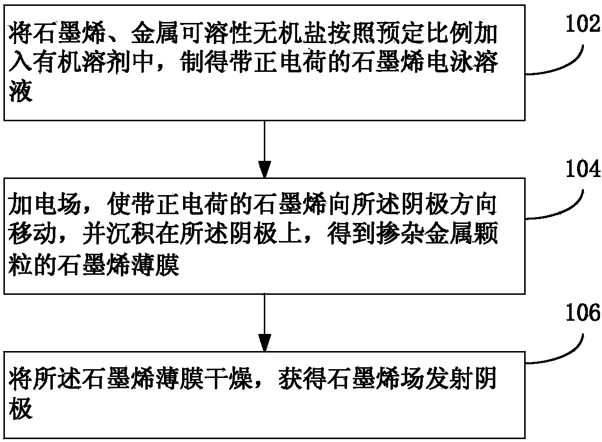
[0025] Such as figure 1 Shown, the graphene field emission cathode preparation method of the present application, an embodiment thereof, comprises the following steps:

[0026] Step 102: Prepare graphene electrophoresis solution.

[0027] Graphene and metal soluble inorganic salts (charge additives) are added to the organic solvent according to a predetermined ratio, and ultrasonically dispersed to prepare a uniform and stable graphene electrophoresis solution.

[0028] Graphene includes single-layer graphene, multi-layer graphene or a mixture of single-layer graphene and multi-layer graphene. The lateral size of graphene is preferably 500 nm-10 μm, and it can be prepared by chemical vapor deposition or chemical exfoliation (Hummer method). The metal soluble inorganic salts include one or more mixtures of soluble inorganic salts of copper, silver, gold and platinum. In one embodiment, the metal-soluble inorganic salt specifically includes copper nitrate, cuprous nitrate, si...

Embodiment 1

[0045] Graphene prepared by the chemical exfoliation method with a lateral size of 0.5-3μm and a thickness of 0.5-3.7nm is added to absolute ethanol, and 10% Cu(NO3)2 (based on graphene weight) is added, and the graphene concentration is 0.05mg / ml , using an ultrasonic cell disruptor to ultrasonically disperse for 30 minutes to obtain a uniform and stable graphene electrophoresis solution;

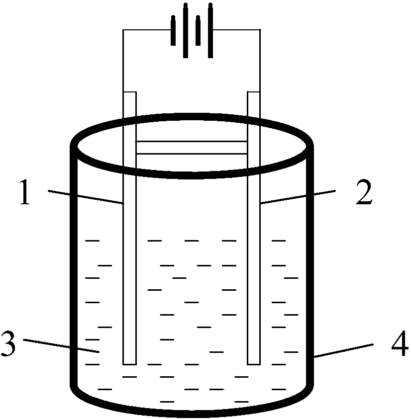
[0046] Select ITO conductive glass and oxygen-free copper sheet as electrodes, clean them with acetone and ethanol for 10 minutes ultrasonically, and dry them with N2 before use. Then, the ITO conductive glass was used as the cathode, and the oxygen-free copper sheet was used as the anode, inserted into the graphene solution, the distance between the cathode and the anode was 1 cm, the DC electrophoresis voltage was 100 V, and the electrophoresis time was 5 min. Graphene film.

[0047] The graphene film was vacuum-dried at 60° C. for 30 min to obtain a graphene field emission cathode.

Embodiment 2

[0049] Add the graphene prepared by the chemical exfoliation method with a lateral size of 0.5-3μm and a thickness of 0.5-3.7nm into isopropanol, add 50% AgNO3 (based on the weight of graphene), and the graphene concentration is 1mg / ml, and use ultrasonic cell disruption Machine ultrasonic dispersion for 2 hours to obtain a uniform and stable graphene electrophoresis solution;

[0050] Select ITO conductive glass and nickel sheet as electrodes, clean them ultrasonically with acetone and ethanol for 10 min, and dry them with N2 before use. Then, the ITO conductive glass was used as the cathode, the nickel sheet was used as the anode, inserted into the graphene solution, the distance between the cathode and the anode was 0.1cm, the DC electrophoresis voltage was 200V, and the electrophoresis time was 30s, and graphite doped with Ag nanoparticles was prepared on the ITO substrate. vinyl film.

[0051] The graphene film was vacuum-dried at 120° C. for 2 h to obtain a graphene fie...


PUM

PropertyMeasurementUnit
concentrationaaaaaaaaaa
sizeaaaaaaaaaa
sizeaaaaaaaaaa

Abstract

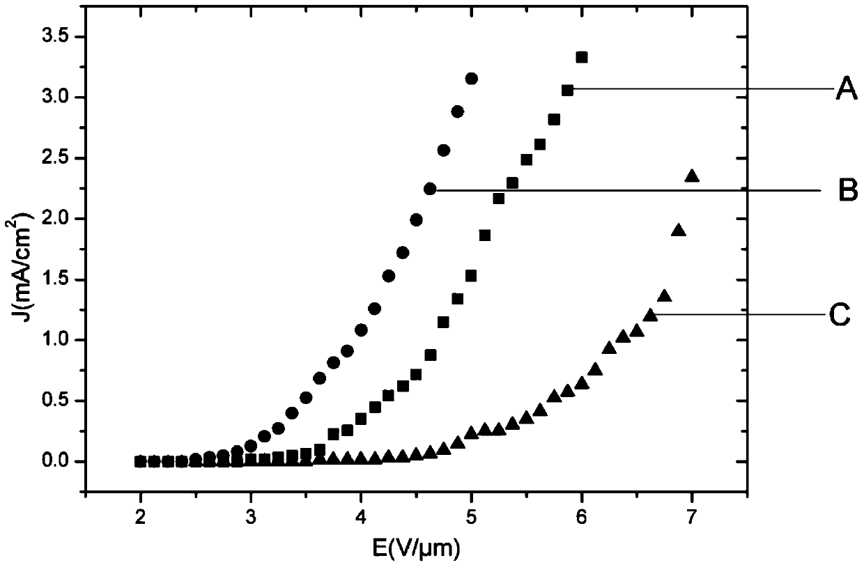
The application discloses a preparation method for a graphene field emitting cathode. The preparation method comprises the following steps of: adding graphene and metal soluble inorganic salts in an organic solvent in a preset ratio to prepare graphene electrophoresis solution with positive charges; using a conductive substrate as a cathode, placing an anode and the cathode in the graphene electrophoresis solution, externally adding an electric field to enable the graphene with positive charges to move towards the direction of the cathode, and deposit on the cathode, so as to obtain a graphene film doped with metal particles; drying the graphene film to obtain the graphene field emitting cathode. The application further discloses a graphene field emitting cathode. The preparation method and the graphene field emitting cathode disclosed by the application are capable of improving the electrical contact characteristic between graphene and a substrate, and improving conduction performance; meanwhile, due to the metal nano-particles, the roughness of the graphene surface is improved, the local electric field intensity of the graphene surface is enhanced, the turn-on electric field of the graphene field emitting cathode is remarkably reduced, and the field emitting current is increased.

Description

technical field [0001] The present application relates to field emission technology, in particular to a method for preparing a graphene field emission cathode and a graphene field emission cathode. Background technique [0002] Graphene is a new type of carbon nanomaterial, which refers to a single layer of carbon atoms tightly packed into a two-dimensional honeycomb lattice structure. It has properties similar to carbon nanotubes, such as extremely excellent electrical conductivity and thermal conductivity, and is very stable. mechanochemical properties. Graphene has a large size-to-thickness ratio and a rich and well-developed edge structure. It is an ideal field emission material and is expected to be applied in field emission fields such as vacuum microwave devices, field emission displays, and X-ray sources. [0003] In order to realize the application of graphene in field emission, graphene must be uniformly deposited on a suitable substrate first. Currently, availab...

Claims


Application Information

Patent Timeline
Patent Type & Authority Applications(China)
IPC IPC(8): H01J9/02H01J1/304
Inventor 洪序达陈垚郑海荣桂建保
Owner SHENZHEN INST OF ADVANCED TECH CHINESE ACAD OF SCI
Learn More