
Glass composite vacuum plate and preparing method thereof

A technology of vacuum panels and composite panels, applied in the field of building energy conservation, to achieve the effects of low production costs, material saving, and weight reduction

Inactive Publication Date: 2015-01-21
戴长虹
View PDF4 Cites 3 Cited by
  • Summary
  • Abstract
  • Description
  • Claims
  • Application Information

AI Technical Summary

Problems solved by technology

[0004] The technical problem to be solved by the present invention is to provide a new type of glass composite vacuum panel and its manufacturing method in view of the defects existing in the existing building insulation panels, thermal insulation panels, and vacuum insulation panels. The manufacturing method of this glass composite vacuum panel The process is simple, and the prepared glass composite vacuum panel can overcome the deficiencies of existing heat insulation panels, vacuum insulation panels and thermal insulation panels, and can effectively ensure the airtightness of the glass composite vacuum panel, prolong the service life, and increase its strength and insulation Heat, sound insulation, fire performance, but also has a good decorative effect

Method used


Image

  • Glass composite vacuum plate and preparing method thereof
  • Glass composite vacuum plate and preparing method thereof

Examples


Embodiment 1

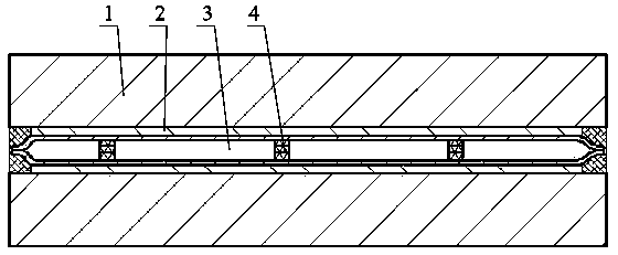
[0039] Example 1: see figure 1, the glass composite vacuum panel is composed of a panel 1, a connecting layer 2, a vacuum chamber 3 and a support 4, and the panel 1 is composed of a glass plate or tempered glass or coated glass or glazed glass or frosted glass with a thickness of 2-6mm; the connection Layer 2 is a high-temperature-resistant adhesive, which can be selected from high-temperature-resistant phenolic resin adhesives, epoxy resin adhesives, silicone resin adhesives, polyimide and other organic adhesives that can be cured at room temperature or high temperature, as well as commonly used inorganic adhesives or organic-inorganic composite adhesives, etc. ; The vacuum chamber 3 is welded by stainless steel plate, stainless iron plate, electro-tinned plate or galvanized plate with a thickness of 0.15-1.0mm; the support 4 is made of metal, ceramics, glass or polymer, and is printed by printing , printing, spraying, mechanical layout, etc. are distributed in a dot matrix i...

Embodiment 2

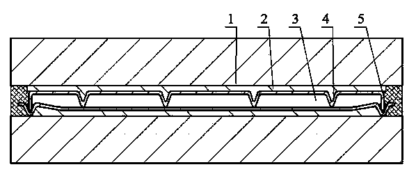
[0040] Example 2: See Example 1 and figure 2 , basically the same as Example 1, the difference is that the metal plate forming the vacuum cavity 3 directly stamps out the grooves for the support 4 and the edge sealing when stamping and forming, and places low-temperature metal solder such as tin, zinc, magnesium in the grooves And its low-melting point alloy, the airtight sealing of the vacuum chamber 3 is completed by brazing in the vacuum furnace.


PUM


Abstract

A glass composite vacuum plate is provided. The glass composite vacuum plate comprises surface plates, connecting layers and a vacuum cavity. The glass composite vacuum plate is characterized in that: the surface plates are glass plates; the connecting layers connect the surface plates and the vacuum cavity into one part; the vacuum cavity is formed by welding thin metal plates; the surface plates and / or the connecting plates provide the vacuum cavity with attached strength and guarantee smoothness of the vacuum cavity under normal pressure; the vacuum cavity is automatically welded and sealed at a high temperature under high vacuum in a vacuum furnace in a mass production manner; supporters are disposed in the vacuum cavity; and the supporters are manufactured separately or directly formed in the vacuum cavity. A manufacturing method of the glass composite vacuum plate is simple in process. The prepared glass composite vacuum plate overcomes the disadvantages of thermal insulation plates and vacuum insulation plates at present, effectively guarantees gas tightness of the vacuum cavity of the glass composite vacuum plate, prolongs the service lifetime of the gas composite vacuum plate, and enhances strength, and thermal-insulation, sound-insulation and fireproof properties.

Description

technical field [0001] The invention relates to the technical field of building energy conservation, in particular to a glass composite vacuum panel and a manufacturing method thereof. Background technique [0002] my country's building energy consumption has accounted for more than 1 / 3 of the energy consumption of the whole society, and it is increasing year by year. The use of thermal insulation building materials is one of the main means to reduce building energy consumption. At present, many materials used for building exterior wall insulation are Class B insulation materials, such as polystyrene, polyurethane, foam rubber and other organic materials. These organic materials have poor heat resistance and are easy to burn. A large amount of toxic smoke can accelerate the spread of the fire; at the same time, organic materials will shrink during a fire, producing burning droplets, causing the tiles on the insulation layer to fall off, which may cause secondary fires and se...

Claims


Application Information

Patent Timeline
Patent Type & Authority Applications(China)
IPC IPC(8): C03C27/08
CPCC03C27/08
Inventor 戴长虹
Owner 戴长虹
Learn More