A kind of gan heterojunction diode device and its preparation method
A heterojunction and diode technology, used in semiconductor/solid-state device manufacturing, semiconductor devices, electrical components, etc., can solve problems such as increased leakage, achieve low turn-on voltage, high forward current, and solve conflicting effects
- Summary
- Abstract
- Description
- Claims
- Application Information
AI Technical Summary
Problems solved by technology
Method used
Image
Examples
Embodiment 1
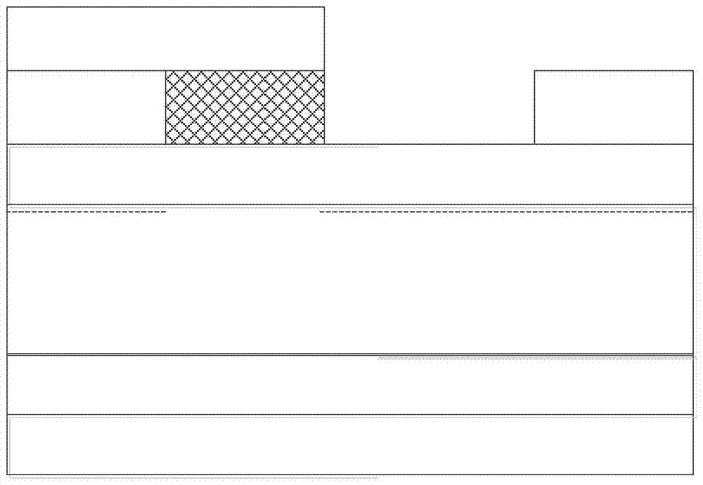
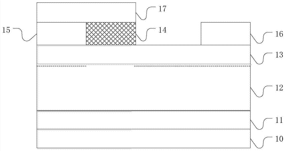
[0050] figure 2 It is a schematic structural diagram of a GaN heterojunction diode device provided in Embodiment 1 of the present invention. Such as figure 2 As shown, the GaN heterojunction diode device described in the embodiment of the present invention includes: a substrate 10, a buffer layer 11 on the substrate 10, a channel layer 12 on the buffer layer 11, and a barrier layer on the channel layer 12. Layer 13, the risk layer 14 on the potential barrier layer 13, the first ohmic anode 15 and the ohmic cathode 16 on both sides of the barrier layer 13 and the risk layer 14, the first ohmic anode is in contact with the risk layer, The second ohmic anode 17 is located on the first ohmic anode 15 and the ohmic layer 14, and the second ohmic anode is in contact with the ohmic metal of the ohmic layer.
[0051] Wherein, the substrate 10 may be silicon carbide, silicon or sapphire.
[0052] The material of the buffer layer 11 can be non-doped GaN, AlN or other III-V nitrides...
Embodiment 2
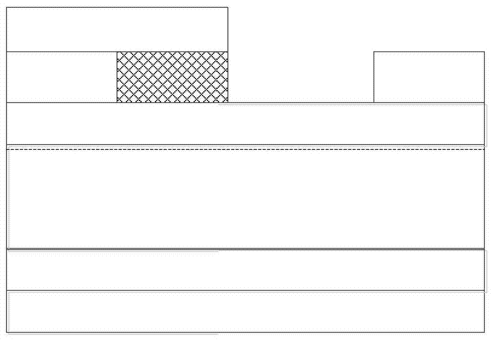
[0072] The GaN heterojunction diode device provided in Embodiment 2 of the invention is based on the GaN heterojunction diode device in Embodiment 1 above, and the difference from Embodiment 1 is that the GaN heterojunction diode device provided in Embodiment 2 is The layer adopts p-type GaN with a thickness of 10-200nm. The advantage of choosing p-type GaN as the capping layer of the GaN heterojunction diode is that a selective etching method can be used in the preparation process, so that the etching of the capping layer can accurately stay on the AlGaN barrier layer.
[0073] Figure 4 It is a schematic structural diagram of a GaN heterojunction diode device provided in Embodiment 2 of the present invention. Such as Figure 4 As shown, the GaN heterojunction diode device described in the embodiment of the present invention includes: a substrate 20, a buffer layer 21 on the substrate 20, a channel layer 22 on the buffer layer 21, and a barrier layer on the channel layer 22...
Embodiment example 3
[0091] The GaN heterojunction diode device provided in Embodiment 3 of the present invention is based on the GaN heterojunction diode device in Embodiment 2 above. The difference from Embodiment 2 is that the GaN heterojunction diode device provided in Embodiment 3 has The first ohmic anode, ohmic cathode, and second ohmic anode are prepared at one time, and the anode and cathode electrode structures are any one or any combination of Ni, Au, Pt, Pd, W, Ag, Cr, ITO alloy. In this embodiment, the first ohmic anode and the second ohmic anode are collectively referred to as ohmic anodes.
[0092] Figure 6 is a schematic structural diagram of a GaN heterojunction diode device provided in Embodiment 3 of the present invention, as shown in Figure 6 As shown, the GaN heterojunction diode device includes: a substrate: 30, a buffer layer 31 on the substrate 30, a channel layer 32 on the buffer layer 31, a barrier layer 33 on the channel layer 32, A layer 34 on the barrier layer 33,...
PUM
 Abstract
Description
Claims
Application Information
 - R&D
- Intellectual Property
- Life Sciences
- Materials
- Tech Scout
- Unparalleled Data Quality
- Higher Quality Content
- 60% Fewer Hallucinations
Browse by: Latest US Patents, China's latest patents, Technical Efficacy Thesaurus, Application Domain, Technology Topic, Popular Technical Reports.
© 2025 PatSnap. All rights reserved.Legal|Privacy policy|Modern Slavery Act Transparency Statement|Sitemap|About US| Contact US: help@patsnap.com


