

Novel sucker rod coupling and production process thereof
A sucker rod coupling, a new type of technology, applied in the direction of drill pipe, drilling equipment, earthwork drilling and production, etc., can solve the problems of coating holes, sucker rod coupling and the inner wall of the oil pipe, wear through the oil pipe, etc., to achieve good Anti-friction performance and wear resistance performance, the effect of achieving friction reduction and wear resistance performance, and improving wear resistance performance
- Summary
- Abstract
- Description
- Claims
- Application Information
AI Technical Summary
Problems solved by technology
Method used
Image

Examples
preparation example Construction
[0049] The preparation technology of novel sucker rod coupling of the present invention comprises the following steps:
[0050] Step 1: Clean and dry the oil on the outer surface of the coupling blank;
[0051] Step 2: Carry out sandblasting, rust removal, roughening and activation on the outer surface of the coupling blank in sequence, and set aside;
[0052] Step 3, uniformly mixing hard tungsten carbide (WC) particles and copper-based alloy powder in a determined ratio by ball milling;
[0053] Step 4, preparing a layer of alloy coating with a thickness of 0.25-1.00 mm on the surface of the coupling blank according to the above-mentioned technical scheme using a pre-bonding process;
[0054] Step 5, drying the coupling after the pre-bonded coating, and then remelting with intermediate frequency induction remelting equipment;
[0055] Step 6: Polish the outer circle of the cooled coupling, grind the chamfer at the junction of the outer circle surface and the end face to be...
Embodiment 1
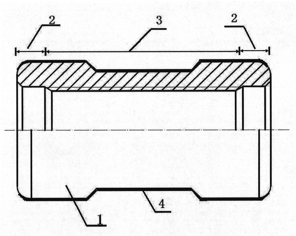
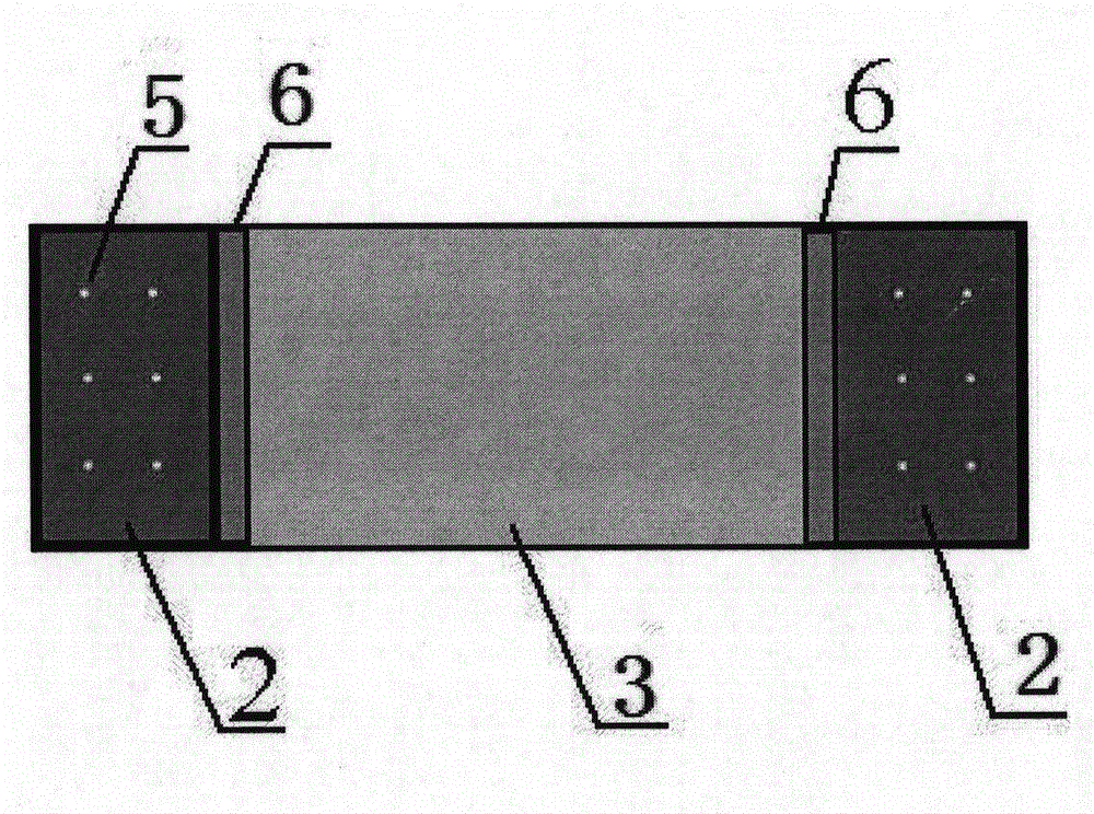
[0060] A copper-based alloy composite coating 2 consisting of 10% by mass of hard tungsten carbide (WC) particles and 90% by mass of a copper-based alloy coating; the copper-based alloy composite coating 2 extends to the next The outer end surface of the hoop base is transitioned with the outer end surface by a circular chamfer, and its length is 15mm. The outer surface of the copper-based alloy composite coating 2 is provided with hemispherical pits 5 with a uniform distribution diameter of 0.05 mm and a depth of 0.06 mm; the particle size of the hard tungsten carbide (WC) particles is 2 μm, and the hard carbide Tungsten (WC) particles are added to copper-based alloy powder by dry ball milling.
[0061] The outer surface of the middle part of the body 1 is provided with a ring-shaped nickel-based alloy coating 3; the two ends of the nickel-based alloy coating 3 are respectively provided with the copper-based alloy composite coating 2 distributed in a ring. The copper-based a...
Embodiment 2
[0063] A copper-based alloy composite coating 2 composed of 25% by mass of hard tungsten carbide (WC) particles and a 75% by mass of copper-based alloy coating; the copper-based alloy composite coating 2 extends to the next The outer end surface of the hoop base is transitioned with the outer end surface with a circular arc chamfer, and its length is 19mm. The outer surface of the copper-based alloy composite coating 2 is provided with uniformly distributed diameters of 0.25 mm and a depth of 0.09 mm hemispherical pits 5; the particle size of the hard tungsten carbide (WC) particles is 7 μm, and the hard carbide Tungsten (WC) particles are added to copper-based alloy powder by dry ball milling.
[0064] The outer surface of the middle part of the body 1 is provided with a ring-shaped nickel-based alloy coating 3; the two ends of the nickel-based alloy coating 3 are respectively provided with the copper-based alloy composite coating 2 distributed in a ring. The copper-based al...
PUM
| Property | Measurement | Unit |
|---|---|---|
| Depth | aaaaa | aaaaa |
| Granularity | aaaaa | aaaaa |
| Granularity | aaaaa | aaaaa |
Abstract
Description
Claims
Application Information