
Preparation method and application of paper-based self-power supply biosensor

A biosensor, self-powered technology, applied in the field of low-cost on-site instant detection, portable field, can solve the problems of energy dependence, expensive instruments, limited application and development, etc., to shorten the test time, avoid the denaturation of the enzyme, and reduce the test detection The effect of this

Inactive Publication Date: 2015-04-22
UNIV OF JINAN
View PDF6 Cites 26 Cited by
  • Summary
  • Abstract
  • Description
  • Claims
  • Application Information

AI Technical Summary

Problems solved by technology

However, the above-mentioned methods are expensive, complicated to operate, and have a strong dependence on energy, which is not conducive to on-site detection anytime and anywhere, which limits its current application and development.

Method used


Image

  • Preparation method and application of paper-based self-power supply biosensor
  • Preparation method and application of paper-based self-power supply biosensor
  • Preparation method and application of paper-based self-power supply biosensor

Examples


Embodiment 1

[0034] Embodiment 1: heavy metal ion Hg in groundwater 2+ detection

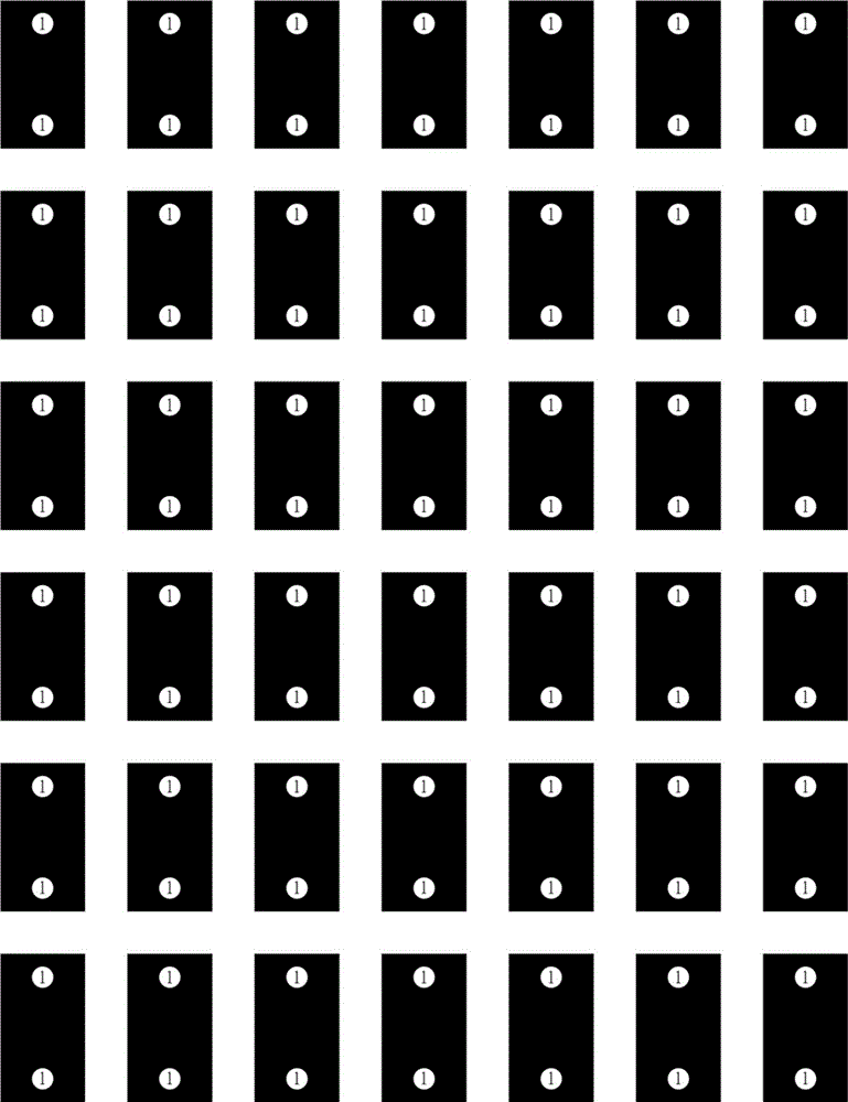
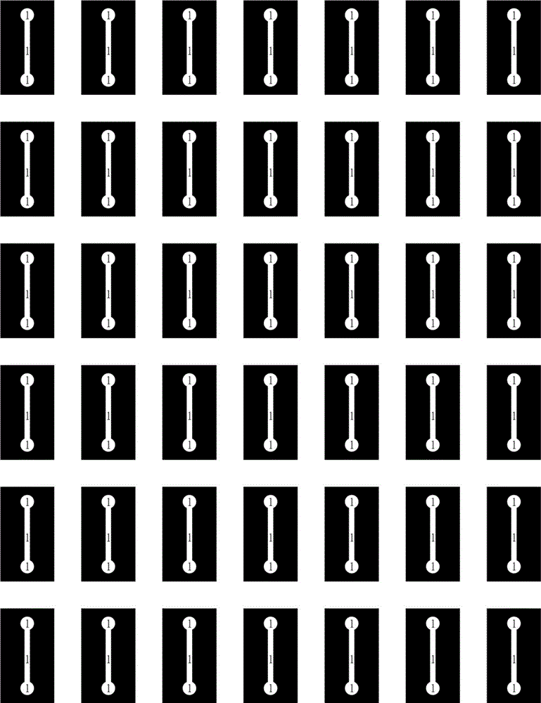
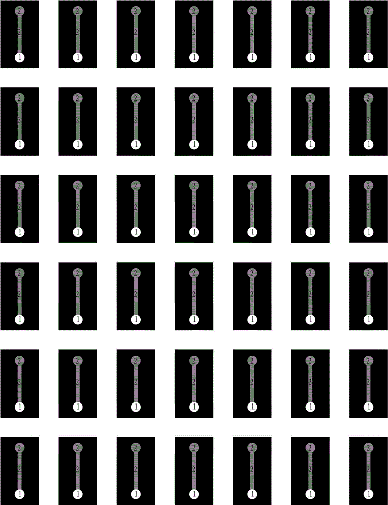
[0035] (1) Use Adobe Illustrator CS4 software on the computer to design a three-dimensional hollow channel microfluidic paper chip, in which the size of a single device is 35×20mm, and they are wax batch printing patterns A, and the samples are as attached figure 1 As shown, the wax batch printing pattern B, the style is attached figure 2 As shown, the wax batch printing pattern C, the style is attached image 3 and 4 As shown, and wax batch printing pattern D, the style is attached Figure 5 As shown, the two circular areas on wax pattern A are the paper anode and the solution inlet respectively, with a diameter of 5mm, the channel width on wax pattern B is 2mm, and the length is 20mm, the diameter of the circular area is 5mm, and the channel on wax pattern C The width is 2mm, the length is 20mm, the diameter of the circular area is 5mm, and the diameter of the circular area (paper cathode) on the wax ...

Embodiment 2

[0044] Embodiment 2: heavy metal ion Ag in underground river water + detection

[0045] (1) Use Adobe Illustrator CS4 software on the computer to design a three-dimensional hollow channel microfluidic paper chip, in which the size of a single device is 35×20mm, and they are wax batch printing patterns A, and the samples are as attached figure 1 As shown, the wax batch printing pattern B, the style is attached figure 2 As shown, the wax batch printing pattern C, the style is attached image 3 and 4 As shown, and wax batch printing pattern D, the style is attached Figure 5 As shown, the two circular areas on wax pattern A are the paper anode and the solution inlet respectively, with a diameter of 5mm, the channel width on wax pattern B is 2mm, and the length is 20mm, the diameter of the circular area is 5mm, and the channel on wax pattern C The width is 2mm, the length is 20mm, the diameter of the circular area is 5mm, and the diameter of the circular area (paper cathode) ...


PUM

PropertyMeasurementUnit
Diameteraaaaaaaaaa

Abstract

A preparation method and an application of a paper-based self-power supply biosensor are provided. The invention discloses a three-dimensional hollow channel microfluidic paper chip adapter sensor having the advantages of simple operation, low cost and self-power supply and successfully used for on-site detection. The sensor successfully introduces a biofuel cell into a three-dimensional hollow channel microfluidic paper chip, utilizes a catalytic effect of a biological fuel cell cathode and anode on a substrate to voluntarily generate an electrical signal, and gets rid of limits on external power supply equipment. The biofuel cell anode prepared by growing gold improves the conductivity of the electrodes, and glucose dehydrogenase is immobilized on the anode; the biofuel cell cathode adopts a carbon nanotube-platinum nano composite material for catalyzing oxygen to reduce, and glucose is used as a fuel; mutual recognition between an adapter and heavy metal ions is generated on the gold-anode; the current intensity is detected by an electrochemical workstation, and thus the heavy metal ions in water are detected.

Description

technical field [0001] The invention relates to a portable, low-cost on-site instant detection technology field. A portable self-powered biosensor based on a hollow channel microfluidic paper chip is constructed. The self-powered biosensor uses a biofuel cell as a core component and combines a suitable It has been successfully used in the determination of trace heavy metal ions in water samples. Background technique [0002] Water heavy metal ion pollution refers to the pollution of water bodies caused by pollutants containing heavy metal ions entering water bodies. Heavy metal wastewater (containing chromium, cadmium, copper, mercury, nickel, zinc and other heavy metal ions) produced in industrial production processes such as mining and metallurgy, machinery manufacturing, chemical industry, electronics, and instrumentation is the most serious water pollution and the most harmful industry to humans. One of the wastewater. Heavy metals in wastewater cannot be decomposed an...

Claims


Application Information

Patent Timeline
IPC IPC(8): G01N27/26
Inventor 于京华王衍虎葛慎光李帅高超民颜梅刘海云张丽娜张彦
Owner UNIV OF JINAN
Learn More