Pyrolysis device for carbonaceous substance

A pyrolysis and material technology, applied in the removal of gas pollutants, catalytic conversion of impurities, gas purification, biofuels, etc., can solve the problems of easy deactivation of catalysts, high tar dust content, and difficulty in stable operation, etc., to achieve simplification Effects of pyrolysis process flow, improved separation efficiency, and good industrial application prospects

Inactive Publication Date: 2015-05-20
INST OF PROCESS ENG CHINESE ACAD OF SCI
View PDF11 Cites 10 Cited by
  • Summary
  • Abstract
  • Description
  • Claims
  • Application Information

AI Technical Summary

Problems solved by technology

[0008] The purpose of the present invention is to overcome the fact that the pyrolyzer, the gas-solid separator and the catalytic reactor are independent, and under high temperature conditions, the low dust removal efficiency leads to pipel

Method used


Image

  • Pyrolysis device for carbonaceous substance
  • Pyrolysis device for carbonaceous substance
  • Pyrolysis device for carbonaceous substance

Examples


Embodiment 1

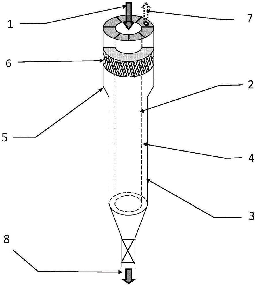
[0035] Pulverized coal with a particle size of 200 meshes, after drying at 105 °C, is added to the inner tube 2 of the pyrolyzer from the top feed port 1 of the pyrolyzer. In the range of ℃, the pulverized coal undergoes a pyrolysis reaction, and the gaseous products are led out through the inner tube with an average filter diameter of 0.5 mm) into the gas collection chamber 4 between the double casings. The high-temperature pyrolysis gas flows upward in the gas collection chamber, and passes through the The diameter-expanding section 5 and the filter layer 6 of the outer tube are discharged from the gas-phase product overflow port 7, and the pyrolysis gas and the pyrolysis oil are separated after the cooling treatment; The coke removal operation is performed at the bottom of the decoking device, so that the semi-coke is released from the coke removal port 8, and the coke quenching treatment is performed. The pyrolysis oil and gas treatment and collection technology and coke q...

Embodiment 2

[0038] Pulverized coal with a particle size of less than 1mm, after drying at 105°C, adopts the mode of internal heating and pyrolysis, and mixes with quartz sand with an average particle size of 2.5mm at 950°C at the top inlet 1 of the pyrolyzer, and adds In the inner tube 2 of the pyrolyzer, quartz sand is used as the heat carrier to heat the pulverized coal particles. pyrolysis reaction. The generated high-temperature pyrolysis gas is filtered by the inner tube (filter diameter ~ 0.45mm), and enters the gas collection chamber 4 between the double casings. 5 and the filter layer 6 are discharged at the gas-phase product overflow port 7, and the pyrolysis gas and the pyrolysis oil are separated through a cooling treatment. Coke quenching, pyrolysis gas treatment and collection technology related to pyrolysis, as well as quartz sand and pyrolysis semi-coke separation and heat carrier circulation technology can be processed in the existing mature way.

Embodiment 3

[0040] The mixed waste biomass of pine wood chips, sawdust and rice husks dried at 105°C is crushed by a high-speed pulverizer and added from the feed inlet at the top of the pyrolyzer. In the external heating mode, the temperature of the inner tube of the pyrolyzer is increased When the temperature is kept in the range of 400-750°C, the biomass undergoes a pyrolysis reaction, and the pyrolysis high-temperature gaseous products are exported through the filtration of the inner tube (the filter diameter is between 0.1-0.5mm), and enter the gas collection chamber 4 between the double casings , the high-temperature pyrolysis gas flows upward in the gas collection chamber, passes through the diameter expansion section 5 and the filter layer 6 of the outer tube, and is discharged at the gas-phase product overflow port 7, and separates the pyrolysis gas and the pyrolysis oil through cooling treatment; After the oil shale powder in the inner wall of the disintegrator reaches the predet...


PUM

PropertyMeasurementUnit
Particle sizeaaaaaaaaaa

Abstract

The invention relates to a pyrolysis device for a carbonaceous substance. In a pyrolysis process, the device can realize gas-solid separation and catalytic quenching and tempering synchronously. In the existing pyrolysis technology, gas-solid separation equipment of high temperature pyrolysis gas, catalytic quenching and tempering equipment and a pyrolysis device are independent to each other. Under the restriction of temperature drop outside the pyrolysis device, high-boiling point tar precipitates out, and dust cannot be effectively removed, thus causing dust entrainment and catalyst deactivation. And along with tar precipitation and accumulation, the dust also results in equipment and pipeline blockage. The invention is characterized in that the pyrolysis device provided by the invention has a double-layer structure, the pyrolysis gas produced by pyrolysis is subjected to three-level gas-solid separation measures, i.e. filtration by a pyrolysis device inner layer 2, separation by a gas collection chamber's diameter expanding segment 5 and filtration by a filtration layer 6, efficient gas-solid separation is realized in the pyrolysis device, and dust entrainment of oil gas products can be avoided. At the same time, a catalyst can be added into the filtration layer 6 to simplify the catalytic pyrolysis process and realize quenching and tempering of pyrolytic oil gas products.

Description

technical field [0001] The invention relates to the technical field of solid energy chemical industry. Specifically, the present invention relates to a pyrolysis device for carbonaceous substances, which has a double-layer structure and can realize the integration of pyrolysis, dust removal and catalytic conditioning. Background technique [0002] Carbon-containing substances, such as coal, biomass, oil shale, etc., are obtained through pyrolysis process to produce pyrolysis oil and gas products, which is an effective way for high value-added utilization of solid energy and efficient utilization of energy cascades. The main problems existing in the current pyrolysis process are low high-temperature gas-solid separation efficiency and serious dust entrainment in high-temperature pyrolysis gas, which will cause blockage of equipment and pipelines and affect the stable operation of equipment; at the same time, the collected pyrolysis oil dust content is high , need further ded...

Claims


Application Information

Patent Timeline
IPC IPC(8): C10B1/00C10B57/00
CPCC10B49/02C10B49/16C10B51/00C10B53/02C10B53/04C10B53/06C10B57/00C10K1/002C10K1/024C10K1/34Y02E50/10
Inventor 张锁江李益吕兴梅李春山
Owner INST OF PROCESS ENG CHINESE ACAD OF SCI
Why Eureka
Try Eureka