
Stainless steel magnetic field regulating device

A technology of stainless steel and magnetic modulation, applied in the direction of electromechanical devices, electromechanical transmission devices, permanent magnet clutches/brakes, etc., can solve the problems of poor creep resistance, complicated manufacturing process, low degree of polymerization, etc., and achieve good machining performance and welding performance, enhance the magnetic field modulation effect, and expand the effect of the application field

Inactive Publication Date: 2015-07-01
JIANGSU UNIV
View PDF7 Cites 23 Cited by
  • Summary
  • Abstract
  • Description
  • Claims
  • Application Information

AI Technical Summary

Problems solved by technology

[0004] In the Chinese invention patent 200810036390.2, it is mentioned a magnetic modulation device that arranges magnetically conductive materials and non-magnetically conductive materials closely along the circumferential direction. The non-magnetically conductive material is epoxy resin, but the magnetic modulation with epoxy resin as the substrate However, the device has the disadvantages of low overall impact strength, poor heat resistance, and is not suitable for outdoor use; an improved magnetic modulation device is mentioned in Chinese invention patent 201010588092.1, and its non-magnetic material is epoxy resin or polyoxymethylene. Screws are penetrated into the non-magnetic material and fixed on the front and rear end plates of the magnetic adjustment ring. This structure increases the mechanical strength of the entire magnetic adjustment device to a certain extent, but the manufacturing process is complicated. In addition, the polyoxymethylene material has a degree of polymerization. The shortcoming is not high, and it is easy to decompose when heated; in the Chinese invention patent 201210432030.0, an I-shaped composite magnetic adjustment device is mentioned. The magnetic adjustment pole pieces are made into an I-shaped structure to increase the contact area with non-magnetic materials, but Its non-magnetic material adopts nylon or epoxy resin, and nylon has the disadvantages of poor creep resistance, easy water absorption, and poor dimensional stability; the above-mentioned magnetic adjustment devices are mostly manufactured by mold casting and machining methods, but its The polymer materials used (epoxy resin, nylon, polyoxymethylene) have the disadvantages of poor dimensional stability or poor machining performance, while the cost of mold casting is relatively high; and the magnetic adjustment mentioned in US2011 / 0012458 A1 In the device, it does not give a detailed description of the selection of non-magnetic materials, and the manufacturing process adopts mold casting with high cost. In addition, the superposition form of the magnetic materials is tangentially superimposed, and this superposition direction cannot be optimal. Good to reduce the loss of the magnetic adjustment device

Method used


Image

  • Stainless steel magnetic field regulating device
  • Stainless steel magnetic field regulating device
  • Stainless steel magnetic field regulating device

Examples


Embodiment 1

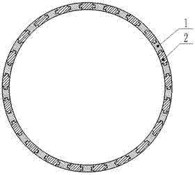
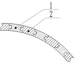
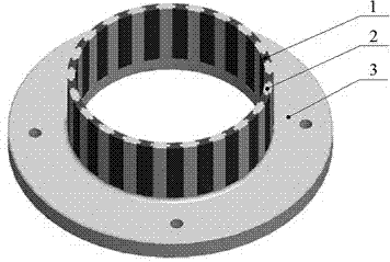
[0053] Example 1: The stainless steel magnetic adjustment device can be used in the cylindrical magnetic transmission device. The magnetic adjustment device is nested with the main and driven rotors, and is located between the main and slave rotors to form a uniform internal and external air gap to achieve radial adjustment. Magnetism, the magnet adjustment pieces 13 are stacked axially or tangentially to form the magnet adjustment block 1 (see Figure 4 , 5 , Figure 9 and Figure 14 ); (1) Applied to the barrel-type magnetic adjustment asynchronous magnetic coupling (see Figure 28 ) in the working principle: the active rotor 9 drives the P 1 Opposite permanent magnet 6 with n 1 rotate at a rotational speed, forming a rotational speed of n 1 , number of pole pairs P 1 Rotating magnetic field, the number of passes is P 2 After the magnet block 1 is modulated, its rotational speed and distribution will change to form a pole pair number P 3 , speed is n 2 The new rotat...

Embodiment 2

[0054] Embodiment 2: The stainless steel magnetic adjustment device can be used in the disc type magnetic adjustment asynchronous magnetic coupling (see Figure 30 ), the magnetic adjustment disk is parallel to the main and driven disks, and a uniform left and right air gap is formed between the main and driven disks to realize axial magnetic adjustment. The magnetic adjustment pieces 13 are stacked radially or tangentially to form a magnetic adjustment block 1 ( See Figure 21 , 22 , Figure 25 and Figure 27 ); the magnetic modulation principle of this magnetic modulation device is similar to the magnetic modulation device in Embodiment 1, the difference is that the former is axial magnetic modulation, and the latter is radial magnetic modulation.


PUM


Abstract

The invention relates to magnetic drive and in particular relates to a stainless steel magnetic field regulating device. The stainless steel magnetic field regulating device is composed of a magnetic field regulating iron block, a stainless steel substrate and a support frame. The magnetic field regulating iron block and the stainless steel substrate are compounded into an integrated structure, and due to the characteristics of the stainless steel, namely no magnetism, high mechanical strength, good heat resistance, small thermal expansion, good dimensional stability and long-term outdoor usability, and the excellent machinability and weldability of the stainless steel material, the defects of high polymer materials (nylon, epoxy resin and polyformaldehyde) used for common magnetic field regulating devices as substrates are overcome. Due to the corrosion resistance and the high temperature resistance of the stainless steel, the magnetic field regulating device becomes a novel insulating sleeve resistant to corrosion and high temperatures and having a magnetic field regulating function, and will play an important role under working conditions having requirements on high temperatures and corrosion prevention in the industries such as chemical engineering and ships. Besides, based on the magnetic shielding principle of a low-frequency magnetic field and the high mechanical strength of the stainless steel, a new magnetic field regulating device having an excellent magnetic field regulating effect also can be constructed.

Description

technical field [0001] The invention relates to magnetic transmission, in particular to a stainless steel magnetic adjustment device, which can be used in magnetic transmission devices in industries such as coal, chemical industry, shipbuilding, and power generation. Background technique [0002] Magnetic transmission is the integration of electromagnetism and mechanics. It replaces mechanical transmission with the basic theory of modern magnetism, and uses the magnetic force generated by permanent magnet materials or electromagnetic mechanisms to realize a new type of non-contact transmission of force or torque. Technology; Compared with traditional mechanical transmission technology, magnetic transmission technology can achieve: 1) realize non-contact transmission; 2) convert dynamic seal in power transmission into static seal to avoid leakage; 3) can avoid vibration transmission and improve transmission Stability; 4) Eliminate the friction problems existing in traditional...

Claims


Application Information

Patent Timeline
IPC IPC(8): H02K51/00H02K49/10
Inventor 杨超君罗永鑫吕蕾章友京蒋毅一
Owner JIANGSU UNIV
Learn More