Shearing-type piezoelectric composite material

A piezoelectric composite material and shear type technology, which is applied in the direction of material selection and device material selection for piezoelectric devices or electrostrictive devices, can solve problems such as high polarization voltage, endangering personnel safety, and hidden dangers. Achieve the effects of reduced polarization voltage, wide adjustment range, and high integration

Active Publication Date: 2015-08-05
CENT SOUTH UNIV
View PDF6 Cites 24 Cited by
  • Summary
  • Abstract
  • Description
  • Claims
  • Application Information

AI Technical Summary

Problems solved by technology

However, the structure needs to apply a higher polarization voltage; on the one hand, the use of a higher polarization voltage puts forward higher requirements on the polarization equipment, on the other hand, it will also bring certain hidden dangers, endangering the safety of personnel

Method used


Image

  • Shearing-type piezoelectric composite material
  • Shearing-type piezoelectric composite material
  • Shearing-type piezoelectric composite material

Examples


Embodiment 1

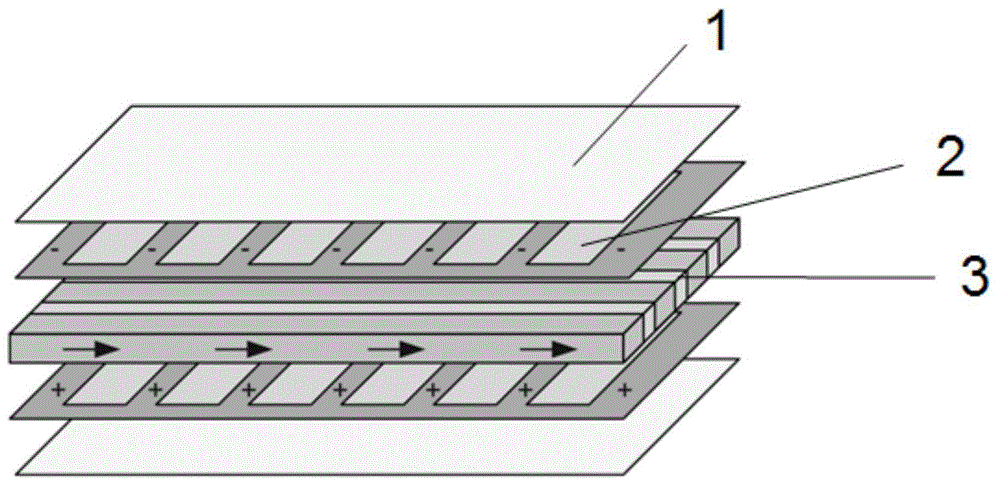
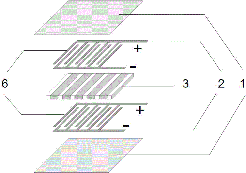
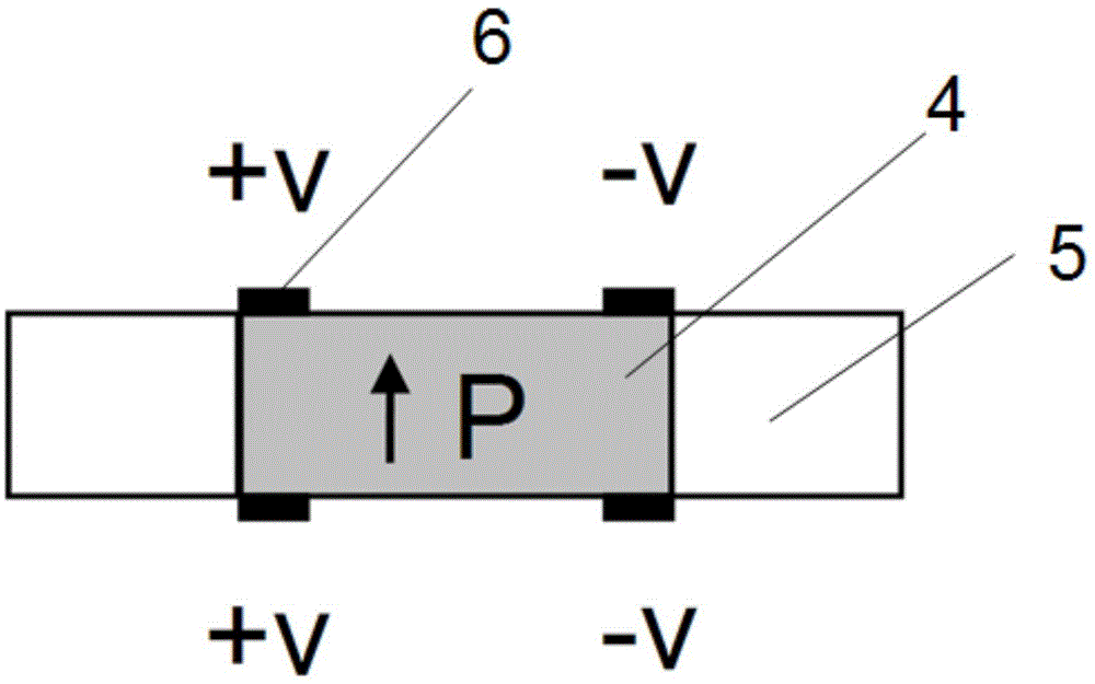
[0034]The lead zirconate titanate piezoelectric ceramics are processed into thin slices of 30mm×10mm×0.5mm. After cleaning and drying, silver paste is coated on the upper and lower surfaces to make electrodes, and a polarization voltage of 1.5kV is applied to obtain 3kV / mm in the thickness direction. The polarizing electric field makes it polarize along the thickness direction. It is cut with a cutting machine, and a piezoelectric ceramic fiber array with a fiber width and a fiber spacing equal to 0.5 mm is obtained by selecting a blade with an appropriate thickness and setting a cutting distance. Fill the array with E-51 epoxy resin, and after curing, obtain a lead zirconate titanate / E-51 epoxy resin composite layer 3 of 30mm×10mm×0.18mm through thinning treatment. In this process, the upper and lower surfaces of the original piezoelectric ceramics Coated silver paste electrodes have been ground off. The interdigitated electrodes were printed on the polyimide film by screen ...

Embodiment 2

[0036] The lead zirconate titanate calcined powder and carbon black powder are mixed with binder, plasticizer, dispersant and solvent, respectively, and made into sheet-shaped green bodies by casting method, which are alternately stacked and then pressed, decarburized and processed. After sintering, lead zirconate titanate sheet matrix is ​​made. The matrix is ​​filled with 711 epoxy resin, and after curing, it is cut to obtain a lead zirconate titanate / E-51 epoxy resin composite layer. In the above process, by controlling the parameters such as the thickness of the green body and the cutting distance, the size of the finally obtained lead zirconate titanate / E-51 epoxy resin composite layer is 10mm×5mm×0.2mm, and the fiber width and fiber spacing are 0.4mm. Use the screen printing method to print interdigitated electrodes on the upper and lower sides of the lead zirconate titanate / 711 epoxy resin composite layer. The distance between the positive and negative fingers of the i...


PUM


Abstract

The invention discloses a shearing-type piezoelectric composite material. The outermost two layers of the composite material structure are flexible insulated thin films, the middle layer is a piezoelectric phase / epoxy resin composite layer, and interdigital electrodes are arranged between the middle layer and the flexible insulated thin films; the positive electrode finger parts and the negative electrode finger parts of the interdigital electrodes are arranged alternatively at equal distances, and the upper interdigital electrode and the lower interdigital electrode are in mirror symmetry and aligned; the finger parts of the interdigital electrodes are parallel to the piezoelectric phase of the piezoelectric phase / epoxy resin composite layer, and the electrode finger parts are located on the upper surface and the lower surface of the edge of the piezoelectric phase and epoxy resin joining surface; and the piezoelectric phase polarization direction is a direction vertical with the composite layer plane. The sheet piezoelectric composite material provided by the invention is thin in thickness, compact in structure, can fit a curved surface structure, can realize a certain degree of flexible deformation, and can be made into a driver, a sensor and the like.

Description

technical field [0001] The invention relates to a shear type piezoelectric composite material. Background technique [0002] In the past ten years, various self-adaptive structures with structural health self-diagnosis, environmental self-adaptation, self-monitoring and other functions have become research hotspots. This kind of composite structure integrating the main structure, sensors and drivers has been widely used in Structural testing, energy harvesting, and vibration control. Piezoelectric ceramics have become the most widely used driver materials in adaptive structures due to their high energy density, fast electromechanical response conversion, and large driving force. [0003] Piezoelectric ceramics are deformed under the action of an external electric field, and are functional materials that can convert electrical energy into mechanical energy. The deformation direction of piezoelectric ceramics is closely related to the direction of the applied electric field:...

Claims


Application Information

Patent Timeline
Patent Type & Authority Applications(China)
IPC IPC(8): H01L41/18
Inventor 张斗陈子琪周科朝朱松陈超
Owner CENT SOUTH UNIV
Why Eureka
Try Eureka