
Nanopowder laser selective melting additive manufacturing system and method

An additive manufacturing and nano-powder technology, applied in the field of nano-powder laser selective melting additive manufacturing system, can solve problems such as difficult to manufacture parts, and achieve the effect of improving selective laser sintering performance and surface quality

Active Publication Date: 2015-09-09
HARBIN INST OF TECH
View PDF6 Cites 23 Cited by
  • Summary
  • Abstract
  • Description
  • Claims
  • Application Information

AI Technical Summary

Problems solved by technology

Conventional powder sintering uses micron-scale powders. Due to the size limitation of the sintered powder itself, conventional selective laser sintering is difficult to manufacture parts with high precision.

Method used


Image

  • Nanopowder laser selective melting additive manufacturing system and method

Examples


specific Embodiment approach 1

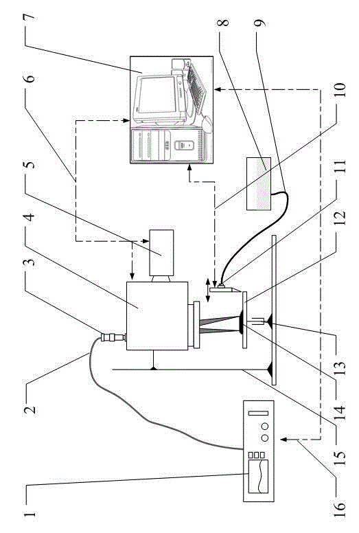
[0025] Specific implementation mode one: as figure 1 As shown, the nano powder laser selective melting additive manufacturing system provided in this embodiment consists of a single-mode fiber laser 1, an output fiber 2, a QBH connector 3, a scanning galvanometer 4, a CCD camera 5, a scanning control line 6, and a control computer 7 , coating chamber 8, conveying pipeline 9, coating motion control device 10, coating knife 11, worktable base 12, lifting device 13, parts 14, bracket 15, and laser control line 16.

[0026] The support 15 is provided with a scanning vibrating mirror 4 and a lifting device 13 , the worktable base 12 is installed on the lifting device 13 , and the scanning vibrating mirror 4 is located above the working table base 12 . The single-mode fiber laser 1 outputs a single-mode Gaussian laser beam with a beam quality less than 1.05, which is connected to the scanning galvanometer 4 through the output fiber 2 and the QBH connector 3, and a CCD camera 5 is us...

specific Embodiment approach 2

[0028] Specific implementation mode 2: In this implementation mode, 100nm copper nanopowder, ethylene glycol, PVP (polyvinylpyrrolidone k30), and deionized water are used to mix and prepare a dispersion in a certain proportion, and the additive manufacturing system is selectively melted by nanopowder laser The coating device coats the surface of the superalloy, in the air environment, using a 1064nm wavelength laser with a power density of 23.1W / mm 2 , scanning speed 20mm / s process parameters for scanning. Copper surface coatings can be produced on superalloys to increase surface functionality and improve quality.


PUM


Abstract

The invention relates to a nanopowder laser selective melting additive manufacturing system and method. The selective melting additive manufacturing system comprises a single mode fiber laser, an output optical fiber, a QBH connector, a scanning galvanometer, a CCD camera, a scanning control line, a control computer, a coating cavity, a conveying pipeline, a coating movement control device, a coating cutter, a workbench base body, a lifting device, a support and a laser control line. In terms of the nanopowder laser selective melting additive manufacturing method, nanopowder is dispersed in solvent through a nanometer dispersion technology, a dispersed solution containing the nanopowder is arranged on the surface of the base body in a coating mode through the coating cutter, and a material is sintered through the selective melting additive manufacturing system. According to the invention, due to the fact that the nanometer material is used as a selective laser sintering material, the selective laser sintering performance and the surface quality can be improved, and surface treatment of the base material can be achieved. Due to the fact that the nanopowder is dispersed in a nanometer dispersion liquid mode, the solvent has oxidation resistance, and sintering can be conducted in the air.

Description

technical field [0001] The invention relates to a nano-powder laser selective melting additive manufacturing system and method, which are applicable to the fields of aerospace, microelectronics, micro-nano structure and the like. Background technique [0002] Selective laser sintering technology is to use the principle of layer-by-layer sintering to manufacture the target part structure through the interaction of laser and powder materials. Conventional powder sintering uses micron-scale powders. Due to the size limitation of the sintered powder itself, conventional selective laser sintering is difficult to manufacture parts with high precision. [0003] Due to its size effect, nanomaterials have advantages and characteristics that conventional materials cannot match. At the same time, due to the size effect of nano-powder, nano-materials have high surface activation energy and significant agglomeration effect. Utilizing and overcoming the effect caused by the size of nano...

Claims


Application Information

Patent Timeline
IPC IPC(8): B29C67/00B22F3/105B33Y30/00B33Y10/00B33Y40/00
CPCY02P10/25
Inventor 王扬刘俊岩王鑫剑
Owner HARBIN INST OF TECH
Learn More