
Method for manufacturing gradient composite electrode for electrical spark rough machining and electrical spark finish machining for laser solid forming

A technology of laser three-dimensional forming and composite electrodes, which is applied in the direction of electric processing equipment, electrode manufacturing, metal processing equipment, etc., can solve the problems of affecting the processing accuracy of workpieces and reducing processing efficiency, so as to improve processing quality, improve uniformity, and improve balance sexual effect

Active Publication Date: 2015-10-14
SHANDONG UNIV OF TECH
View PDF4 Cites 2 Cited by
  • Summary
  • Abstract
  • Description
  • Claims
  • Application Information

AI Technical Summary

Problems solved by technology

At present, two kinds of electrodes with different precision are used to process the workpiece twice successively, and the electrode is replaced in the middle, which reduces the processing efficiency; at the same time, due to the need to clamp the electrodes twice, the difference in the clamping position will also Affect the machining accuracy of the workpiece

Method used


Image

  • Method for manufacturing gradient composite electrode for electrical spark rough machining and electrical spark finish machining for laser solid forming
  • Method for manufacturing gradient composite electrode for electrical spark rough machining and electrical spark finish machining for laser solid forming
  • Method for manufacturing gradient composite electrode for electrical spark rough machining and electrical spark finish machining for laser solid forming

Examples


Embodiment 1

[0034] A Cu-based SiC composite micropowder for an electric discharge tool electrode was prepared according to the following steps in turn:

[0035] a. SiC is made into particles with a particle size of 3um, and the electroless plating solution is made by dissolving 14 mass parts of copper sulfate pentahydrate, 25 mass parts of formaldehyde and 10 mass parts of sodium hydroxide in 1000 mass parts of water, SiC The particles are put into the electroless plating solution for surface electroless copper plating and dried. The mass ratio of SiC particles to electroless plating solution is 1:10 to obtain SiC copper-plated particles; the working temperature of electroless copper plating is 80°C and the time is 3 hours ;

[0036] b. Heating metallic pure Cu to 1150°C to prepare Cu melt;

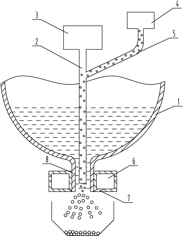
[0037] c. If figure 1 As shown, a conduit 2 is set in the funnel 1, the lower end of the conduit 2 is located at the nozzle 8 at the bottom of the funnel 1, and the upper end is connected to the hi...

Embodiment 2

[0046] The difference between this embodiment and embodiment one is that the particle diameter of the SiC particles in step a is 4um, the mass fraction of copper sulfate pentahydrate in the electroless plating solution is 15 parts, the mass fraction of formaldehyde is 28 parts, hydrogen The mass fraction of sodium oxide is 11 parts; the heating temperature of metallic pure Cu in step b is 1165°C; the gas supply pressure of the gas supply device 6 in step c is 1.3 MPa; the sieve mesh number of the composite micropowder in step d is 125 mesh.

[0047] The slice thickness in step (1) is 0.3 mm; the ultrasonic vibration power in step (2) is 90W, the amplitude is 1.5um; the diameter of the laser beam is 1.5 mm, the laser power is 3.5KW, the scanning speed is 8 mm / s, coaxial The powder feeding amount is 7g / min; in step (3), the beam diameter is 1.5mm, the laser power is 5 KW, the scanning speed is 4mm / s, the laser coaxial powder feeding amount is 7g / min, and the Cu powder diameter is...

Embodiment 3

[0049] The difference between this embodiment and Example 1 is that the particle diameter of the SiC particles in step a is 5um, the mass fraction of copper sulfate pentahydrate in the electroless plating solution is 16 parts, the mass fraction of formaldehyde is 32 parts, hydrogen The mass fraction of sodium oxide is 12 parts; the heating temperature of metallic pure Cu in step b is 1180°C; the gas supply pressure of the gas supply device 6 in step c is 1.4 MPa; the sieve mesh number of the composite micropowder in step d is 150 mesh.

[0050] The slice thickness in step (1) is 0.4mm; the ultrasonic vibration power in step (2) is 100W, the amplitude is 2um; the diameter of the laser beam is 2 mm, the laser power is 4KW, the scanning speed is 9 mm / s, coaxial powder feeding The amount is 8g / min; in step (3), the beam diameter is 2mm, the laser power is 6KW, the scanning speed is 5mm / s, the coaxial powder feeding amount of the laser is 8g / min, the diameter of Cu powder is 80um, a...


PUM

PropertyMeasurementUnit
thicknessaaaaaaaaaa
thicknessaaaaaaaaaa
thicknessaaaaaaaaaa

Abstract

The invention discloses a method for manufacturing a gradient composite electrode for electrical spark rough machining and electrical spark finish machining for laser solid forming and belongs to the technical field of electric discharge machining. The method comprises the steps that a three-dimensional solid model is generated by means of software, the model is sliced and layered, and the parameters of all slice layers are obtained; then, Cu-based SiC composite micro powder is sintered on a vibrating substrate by means of laser according to the shape parameter of the slice layer on the inner side; finally, Cu powder and graphite powder are sintered on a Cu-based SiC composite sediment layer in a mixing mode by means of laser according to the shape parameter of the slice layer on the outer side. The electrode manufactured through the method is provided with a gradient structure, and electricity is discharged firstly by the Cu-based graphite sediment layer located on the outer layer of the electrode so as to achieve rough machining of a workpiece; then finish machining of the workpiece is achieved by means of the Cu-based SiC composite sediment layer of the electrode. Meanwhile, the Cu-based SiC composite micro powder is formed by blowing SiC particles in molten Cu in a dispersed mode by means of nitrogen and then conducting atomization and cooling, in this way, the distribution uniformity of the SiC particles is improved, and the equilibrium of the electric corrosion resistance of the electrode is improved.

Description

technical field [0001] The invention belongs to the technical field of electric discharge machining, and in particular relates to a preparation method of a gradient composite electrode for laser three-dimensional forming electric discharge rough and finish machining. Background technique [0002] Due to the incomparable advantages of other processing methods in processing special performance materials, complex structures and micro parts, EDM technology has been gradually promoted and applied in recent years. In the process of EDM, the electrode material that is melted, gasified, and exploded not only removes the material of the workpiece, but also removes the material of the tool electrode. Loss, while the loss of the tool electrode is directly mapped to the workpiece, affecting its forming accuracy. [0003] In order to improve the forming accuracy of the workpiece, some experts and scholars have invested in the research of tool electrodes. Among them, Associate Professor...

Claims


Application Information

Patent Timeline
Patent Type & Authority Applications(China)
IPC IPC(8): B23H1/04B23H1/06
CPCB22F3/105B23H1/04B23H1/06
Inventor 李丽王东田忠强
Owner SHANDONG UNIV OF TECH
Learn More