Desulfurization and denitrification method for tail gas, used equipment and product application thereof

A technology for desulfurization, denitrification and exhaust gas, which is applied in the field of utilization and recycling of environmental pollutants, and can solve the problems that calcium nitrite is used as a chemical fertilizer and has not been reported in the literature.

Inactive Publication Date: 2015-11-25
陈汇宏 +2
View PDF41 Cites 24 Cited by
  • Summary
  • Abstract
  • Description
  • Claims
  • Application Information

AI Technical Summary

Problems solved by technology

[0014] It is known in the industry that calcium nitrate and ammonium nitrate obtaine...

Method used


Image

  • Desulfurization and denitrification method for tail gas, used equipment and product application thereof
  • Desulfurization and denitrification method for tail gas, used equipment and product application thereof
  • Desulfurization and denitrification method for tail gas, used equipment and product application thereof

Examples


Embodiment 1

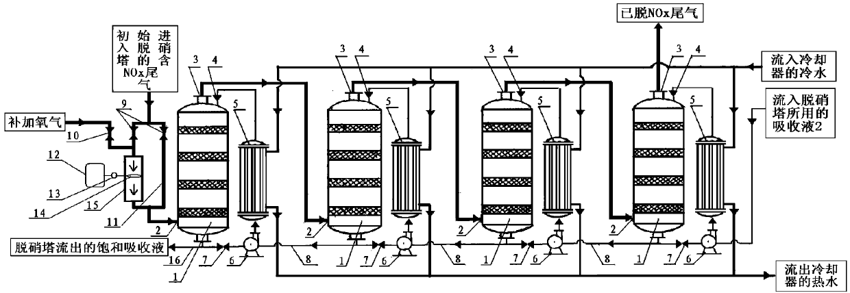
[0119] figure 1 In the combined equipment used in the present invention, on the tail gas inlet pipe interface of the first-stage denitrification tower, a parallel denitrification tower equipment process flow is provided with a parallel pipe section consisting of a shunt straight-through branch pipeline and a shunt control corona discharge branch pipeline. a schematic.

[0120] Such as figure 1 As shown, 1 is the denitrification tower, 2 is the tail gas inlet pipe connection at the bottom of the denitrification tower at each level, 3 is the tail gas outlet pipe connection at the top of the denitrification tower at each level, and 4 is the inlet pipe of the second absorption liquid of the denitrification tower at each level Interface, 5 is the water cooler attached to the denitrification towers at all levels, 6 is the propulsion pump for the second absorption liquid attached to the denitrification towers at all levels, and 7 is the gradually saturated absorption liquid of the s...

Embodiment 2

[0130] Such as Figure 7 as shown, Figure 7 It is one of the desulfurization and denitrification process equipment flow of the desulfurization and denitration tower combination device connected in series after the parallel pipeline section of diversion control discharge oxidation according to the present invention, and before the parallel pipeline section of diversion control discharge oxidation schematic diagram. Such as Figure 7 As shown, the thickest black solid line with arrow points to the flow direction of sulfur-containing nitrate tail gas and supplementary air and oxygen, and the thin black solid line with arrow points to the flow direction of the first absorption liquid and the second absorption liquid Flow direction, where the middle thick black solid line with arrow and pointing is the flow direction of cooling water.

[0131]A combined equipment used in the desulfurization and denitrification method of tail gas, comprising: denitrification tower 1, tail gas in...

Embodiment 3

[0150] The present invention is implemented in the tail gas treatment section of a set of commercially available thermal cracking equipment of a certain brand that annually processes 10,000 tons of waste tires.

[0151] Since the vulcanized rubber in waste tires contains sulfur and the polyamide fiber in waste tires contains nitrogen, the waste tires are subjected to dry distillation and condensation treatment in the thermal cracking equipment, and the non-condensable combustible gas derived from the condenser is then introduced Combustion furnace, the exhaust gas from the combustion furnace, due to the oxidation process of combustion, the sulfur and nitrogen in the tail gas must be mainly sulfur dioxide SO 2 And the form of nitrogen oxide NOx exists. The main parameters of the exhaust emission of this device are: 1) average exhaust humidity 8.30%, 2) average exhaust temperature 80°C, 3) average exhaust velocity 5.62m / s, 4) average exhaust volume 75.00Nm 3 / min, 5) The concen...


PUM


Abstract

The present invention discloses a desulfurization and denitrification method for tail gas, used equipment and product application thereof. According to the method provided by the present invention, an oxidative catalyst is not used in a desulfurization column or a denitration column, or a small amount of the oxidative catalyst with a simplified formula added is used outside the desulfurization column and the denitration column, so that the cost is reduced significantly. The oxidative catalyst is not used in the desulfurization column or the denitration column to avoid the severe corrosion of the desulfurization column and denitration column texture by the material, so that the texture cost of the desulfurization column and the denitration column is reduced significantly; The volume of the processed material is small: only 30%-10% of the material in volume in the desulfurization column and the denitration column, and the cost for equipment corrosion prevention is lowered, so that a small amount of the oxidative catalyst used and a simplified formula can be facilitated.

Description

technical field [0001] The invention belongs to the technical field of recycling and utilization of environmental pollutants, and relates to a tail gas desulfurization and denitrification method, used equipment and application of products thereof. Background technique [0002] In the prior art, the technology for thermal cracking treatment of waste rubber and waste plastics includes: heating dry distillation, condensing dry distillation oil and gas, collecting condensed fuel oil fractions, burning non-condensable combustible gas at the bottom of the cracking furnace, and releasing it from the furnace. Purify the exhaust gas, and then empty the purified exhaust gas. Its characteristic is that the disclosed technology development directions are all focused on how to obtain as much and good oil as possible and recover the combustion heat of combustible gas, and at the same time assess how to clean up the combustion tail gas of the last emptied pyrolysis furnace as much as possi...

Claims


Application Information

Patent Timeline
IPC IPC(8): B01D53/75B01D53/78B01D53/73B01D53/60C02F1/70C09K3/18C08K3/30C04B12/00C05C5/00C05C5/04
Inventor 陈汇宏胡嘉庆沙良宝
Owner 陈汇宏
Why Eureka
Try Eureka