A method for treating flue gas

A flue gas treatment and flue gas technology, applied in separation methods, chemical instruments and methods, dispersed particle separation, etc., can solve problems such as low operating costs, and achieve the effects of improving operating reliability, low operating costs, and simple principles

Active Publication Date: 2017-06-16
CHINA SHENHUA ENERGY CO LTD +2
View PDF7 Cites 0 Cited by
  • Summary
  • Abstract
  • Description
  • Claims
  • Application Information

AI Technical Summary

Problems solved by technology

[0004] In order to overcome the existing flue gas treatment method is difficult to remove F - , Cl - The problems caused by system equipment corrosion, low desulfurization efficiency and difficult wastewater discharge and the removal of F - , Cl - The problem of expensive investment and operating costs brought by ions, the invention provides a flue gas treatment method, which can effectively remove HF, HCl and SO in the flue gas 3 etc., solved the problem of desulfurization absorption tower F caused by flue gas - , Cl - The various problems caused by the enrichment, and the method is simple and low operating cost

Method used


Image

  • A method for treating flue gas
  • A method for treating flue gas

Examples


Embodiment 1

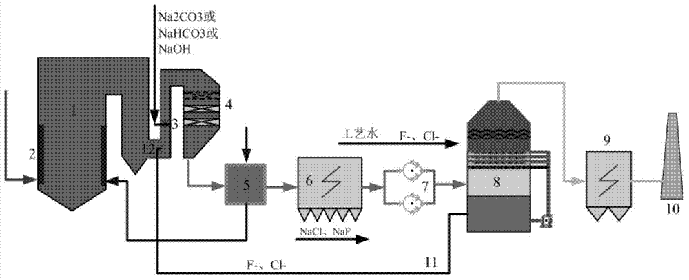
[0033] according to figure 1 In the flow chart shown, the flue gas produced by the combustion of 100 parts by weight of Shenhua bituminous coal in the boiler 1 enters the flue, and an injector 3 with a high-efficiency atomizing nozzle is arranged in the flue, and the injector 3 injects 1.2 wt. The concentration of part is the atomized alkaline solution (Na 2 CO 3 and NaHCO 3 Mixed aqueous solution, as Na 2 CO 3 ), and cooperate with the flue gas flow equalization device to make the atomized solution particles and the flue gas evenly mixed, the flue gas passes through the flue provided with the injector 3 and then continues to enter the SCR denitrification device for denitrification, and then enters the air preheater 5 in turn for denitrification Cool down, enter the electrostatic precipitator 6 for dust removal (remove the solids in the flue gas (including the solid salt of F and Cl generated)), and enter the desulfurization absorption tower 8 through the induced draft fan...

Embodiment 2

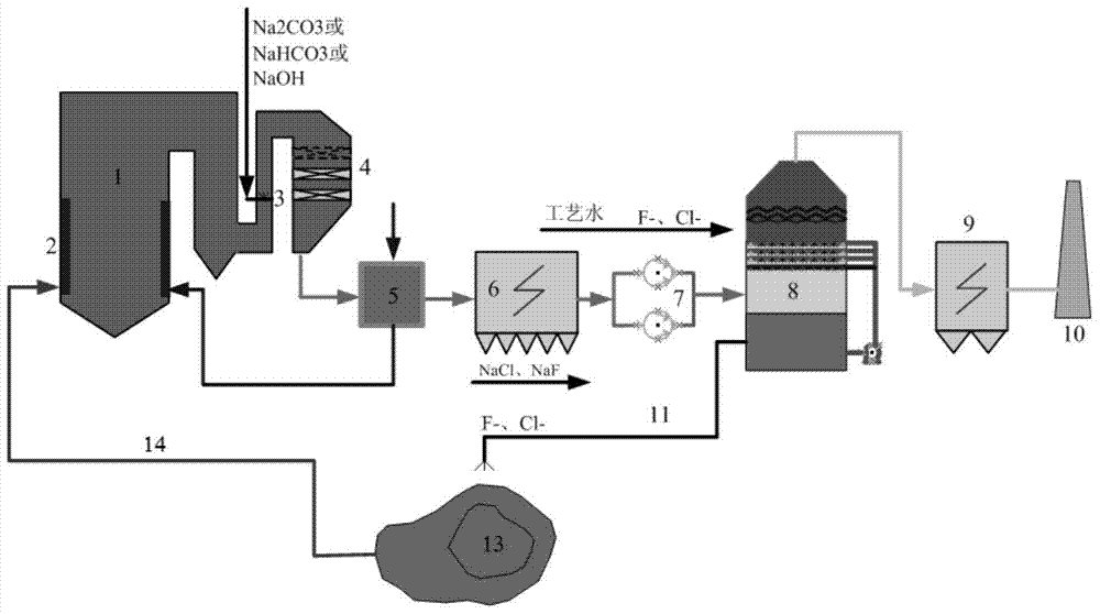
[0036] according to figure 2 As shown in the flow chart, the flue gas produced by the combustion of 100 parts by weight of Shenhua bituminous coal in the boiler 1 enters the flue, and an injector 3 with a high-efficiency atomizing nozzle is arranged in the flue, and the injector 3 injects 1.1 wt. The concentration of one part is the atomized alkaline solution (aqueous solution of NaOH, calculated as NaOH) of 5% by weight, and preferably cooperates with the flue gas equalizing device so that the atomized solution particles are uniformly mixed with the flue gas, and the flue gas passes through and is provided with an injector After the flue of 3, continue to enter the SCR denitration device for denitrification, then enter the air preheater 5 for cooling, and then enter the electric precipitator 6 for dust removal (remove the solids in the flue gas (including the solid salts of F and Cl generated) ), enter the desulfurization absorption tower 8 by induced draft fan 7 and carry o...


PUM


Abstract

The invention relates to the field of gas treatment, and discloses a smoke treatment method. The method comprises the step of performing SCR denitration processing and desulfuration processing on smoke generated by coal combustion, and is characterized by also comprising: contacting the smoke with an alkali solution in an atomized state to convert HF, HCl and SO3 gas in the smoke into solid salt before the SCR denitration processing. According to the method, the HF and HCl in the smoke can be effectively removed, various problems caused by enriching of F<-> and Cl<-> of a desulfuration absorption tower due to introduction of the smoke are solved, and the method is simple and low in operation cost.

Description

technical field [0001] The invention relates to the field of gas treatment, in particular to a flue gas treatment method. Background technique [0002] In the existing thermal power plant flue gas treatment process, the HF, HCl and SO in the flue gas 3 etc. If no effective removal measures are taken, it will be dissolved in the desulfurization tower of the wet flue gas desulfurization system to form F - , Cl - and other highly corrosive ions and continuously enriched, if not controlled, then F - , Cl - Excessive plasma concentration will aggravate the corrosion of system equipment, and at the same time cause the quality of desulfurization slurry to deteriorate, affecting the efficiency of gypsum dehydration and desulfurization. [0003] Therefore, the desulfurization system needs to regularly discharge wastewater. Through flocculation, neutralization, precipitation and other treatment processes, the desulfurization wastewater is treated, and the treated wastewater is reu...

Claims


Application Information

Patent Timeline
Patent Type & Authority Patents(China)
IPC IPC(8): B01D53/78B01D53/68B01D53/50B01D53/56
Inventor 王祖林魏书洲郝剑张翼刘喆彰金宝李永和邵建林谢占军卢权
Owner CHINA SHENHUA ENERGY CO LTD
Why Eureka
Try Eureka