Micro silicon-based capillary pump loop cooler

A technology of capillary pump and cooler, which is applied in the field of silicon-based capillary pump circuit micro-cooler, can solve the problems of thermal stress concentration, reduce heat dissipation efficiency, etc., and achieve the effects of promoting heat dissipation and cooling, reducing flow resistance of working fluid, and eliminating hot spots

Inactive Publication Date: 2015-12-16
江苏中圣压力容器装备制造有限公司
View PDF6 Cites 16 Cited by
  • Summary
  • Abstract
  • Description
  • Claims
  • Application Information

AI Technical Summary

Problems solved by technology

This heat dissipation mode will introduce additional contact thermal resistance during the connection process, reducing its heat dissipation efficiency, and has great limitations in reducing local "hot spots" on the surface of the device; at the same time, it may also lead to thermal stress concentration due to material compatibility The problem is more serious when the temperature distribution of the device itself is uneven

Method used


Image

  • Micro silicon-based capillary pump loop cooler
  • Micro silicon-based capillary pump loop cooler
  • Micro silicon-based capillary pump loop cooler

Examples


Embodiment 1

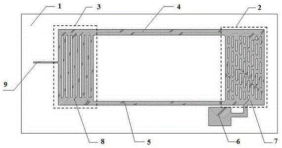
[0036] The silicon-based CPL micro-cooler of the present invention is combined with heat-resistant borosilicate glass and silicon chips through electrostatic bonding. Among them, microchannels, micro-rib array capillary structures, and liquid storage chambers are etched on the side where the silicon wafer contacts the borosilicate glass, and vacuum / liquid injection is processed on the borosilicate glass wafer at the position corresponding to the silicon wafer. hole.

[0037] The semiconductor silicon chip structure that constitutes the silicon-based CPL microcooler is as follows: figure 1 As shown, the evaporator 2, the condenser 3, the vapor phase channel 4, the liquid phase channel 5 and the liquid storage tank 6 are etched on one side of the silicon wafer 1 by the MEMS etching process, and the evaporator contains a rectangular micro-rib array capillary structure 7. The condenser contains microchannels 8 and liquid injection channels 9, and the etched parts are marked with ...

Embodiment 2

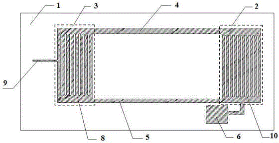
[0043] For the evaporator of the capillary pump loop, in addition to the micro-rib array capillary structure described in Embodiment 1, it can also be figure 2 A microchannel array structure 10 similar to a condenser is shown. and figure 1 The etched structure of the silicon wafer shown is similar, and the hydraulic diameters of the vapor phase channel, liquid phase channel, condenser and evaporator microchannels are 320 μm, 285.7 μm, 267.7 μm and 218.2 μm, respectively.

Embodiment 3

[0045] In this embodiment, the vapor phase passage 4 and the liquid phase passage 5 of the capillary pump circuit microcooler described in Embodiment 1 and Embodiment 2 are subjected to variable cross-section processing, so that the cross-sectional area of ​​the vapor phase passage is from the evaporator to the condenser. It increases linearly, the channel width increases from 600 μm to 1200 μm, and the corresponding channel hydraulic diameter increases from 300 μm to 342.9 μm; while the cross-sectional area change of the liquid phase channel is just opposite to that of the vapor phase channel, and it is linear from the evaporator to the condenser Decreasing the change, the channel width decreases from 700 μm to 300 μm, and the corresponding channel hydraulic diameter decreases from 311.1 μm to 240 μm. After the above adjustments, it is beneficial to enhance the spontaneous movement effect of the cooling working medium in the vapor phase channel and the liquid phase channel, an...


PUM

PropertyMeasurementUnit
diameteraaaaaaaaaa
diameteraaaaaaaaaa

Abstract

The invention relates to a micro silicon-based capillary pump loop cooler. The micro silicon-based capillary pump loop cooler is characterized by comprising a pair of semiconductor silicon chips and heatproof boron silicate glass which are bonded, wherein a surface of the silicon chip (1) contacting with the boron silicate glass is etched with an evaporator (2), a condenser (3), a vapor phase channel (4), a liquid phase channel (5), a liquid storage chamber (6) and a silicon chip vacuum-pumping/liquid injection channel (9), a vacuum-pumping/liquid injection hole (12) is processed on the boron silicate glass (11), the evaporator (2) and the condenser (3) are respectively arranged at two ends of the silicon chip (1) and are mutually communicated through the vapor phase channel (4) and the liquid phase channel (5) to realize heat exchange, the liquid storage chamber (6) is communicated with a liquid inlet of the evaporator (2), and the silicon chip vacuum-pumping/liquid injection channel (9) is communicated with vacuum-pumping/liquid injection hole (12) processed on the boron silicate glass (11). The micro silicon-based capillary pump loop cooler has advantages of simple structure, convenient manufacturing and good heat radiation effect.

Description

technical field [0001] The invention relates to a micro-cooler, especially an integrated silicon-based capillary pump circuit (CPL), which is composed of a pair of semiconductor silicon wafers and heat-resistant borosilicate glass bonded together by electrostatic bonding process The high-efficiency micro-cooling device has good application prospects in the field of temperature control of microelectronic devices, specifically a silicon-based capillary pump circuit micro-cooler. Background technique [0002] With the rapid development of the semiconductor information and communication industry, the high integration and miniaturization of various related products and equipment has become an important development trend, which leads to the rapid increase of the heat load of microelectronic devices and the problem of excessive heat generation. Seriously affect the reliability of its work and even the entire system. At the same time, the uneven heating of the microelectronic devic...

Claims


Application Information

Patent Timeline
Patent Type & Authority Applications(China)
IPC IPC(8): H01L23/427B81C1/00B81B7/00
Inventor 郭宏新屈健刘丰孙田
Owner 江苏中圣压力容器装备制造有限公司
Why Eureka
Try Eureka