
An online detection and correction system for laser shock processing based on workpiece vibration frequency

A vibration frequency, laser shock technology, applied in the direction of optical testing flaws/defects, can solve problems such as affecting quality, target material damage, reducing crack growth rate, etc., to improve impact speed and efficiency, low cost, and low external environment requirements. Effect

Inactive Publication Date: 2018-08-28
LIANYUNGANG NORMAL COLLEGE
View PDF7 Cites 2 Cited by
  • Summary
  • Abstract
  • Description
  • Claims
  • Application Information

AI Technical Summary

Problems solved by technology

[0002] Laser shock treatment is an emerging material surface strengthening technology, which plays an irreplaceable role in some occasions and has a huge economic market; in many technical fields, such as thin film laser sputtering technology, isotope laser enrichment technology, laser trace Laser shock treatment is involved in analysis technology and other research; laser shock spraying (LSP) is also called laser shock treatment, which uses intense pulsed laser to generate shock waves for strengthening treatment. In this process, the surface of the workpiece is formed by an opaque layer (energy Absorbing layer) and a transparent layer (constraining layer) covering, during operation, a high-power pulsed laser beam is focused on the surface of the workpiece; the laser pulse passes through the transparent coating and is absorbed by the absorbing layer, causing rapid ablation of the absorbing layer, Plasma is generated, and the plasma is ejected from the surface of the workpiece to generate high-amplitude pressure shock waves. The shock waves are finally combined to cause plastic strain on the workpiece, resulting in deformation of the workpiece and residual compressive stress. It is these residual compressive stresses in the workpiece that effectively reduce the pressure of the workpiece. The crack growth rate in , thus improving the fatigue characteristics of the workpiece; however, since the laser shock intensity and the material absorption layer cannot achieve a perfect match, when the laser intensity is too large or the absorption layer is coated too thin, the target material will be damaged by the laser , affect the quality; at present, the most direct detection method for the quality of LSP is to carry out the high-frequency fatigue test HCF, so as to obtain the fatigue life after LSP treatment, and use it as the basis for quality judgment, but this test is destructive. It is impossible to popularize and apply it in production, and the HCF test is a random sampling technique, which is a rough statistical measurement and cannot realize online quality monitoring; The research is very necessary. General Corporation of the United States applied for two patents in 2005 and 2007: a system and method for monitoring laser shock treatment, and a laser shock strengthening system for time-of-flight monitoring. The former is based on the plasma generated by laser shock. The line spectrum characteristics of the radiation, the latter realizes the real-time online detection of the laser shock according to the time-of-flight characteristics of the shock wave during the laser shock process, but these two methods are not only costly but also have relatively high requirements on the environment. Weakness, temperature changes, air humidity, etc. will affect the characteristics of the spectral line and the flight time of the shock wave, resulting in detection errors; based on the above reasons, it is necessary to develop a better device or system for detecting the quality of laser shock processing

Method used


Image

  • An online detection and correction system for laser shock processing based on workpiece vibration frequency

Examples


Embodiment Construction

[0011] The technical solution of this patent will be described in further detail below in conjunction with specific embodiments.

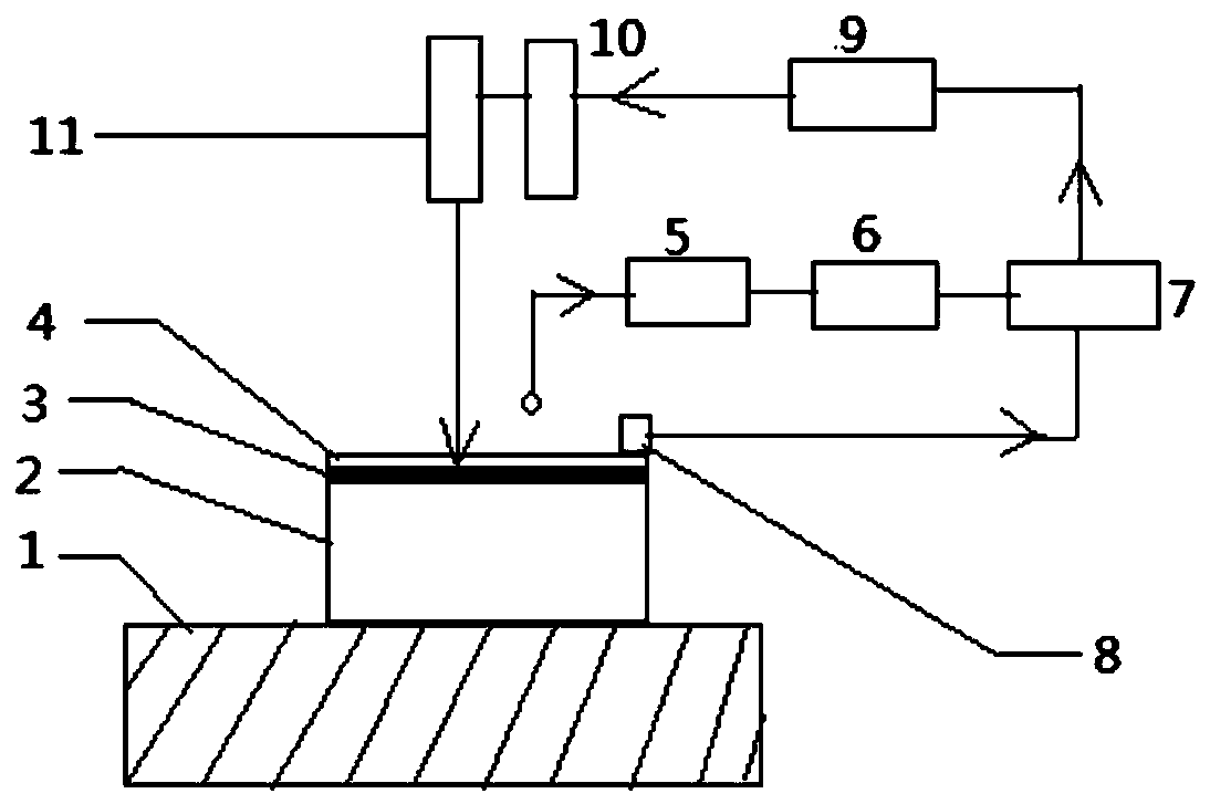
[0012] See figure 1 , An online detection system for laser shock processing based on the vibration frequency of the workpiece, including a delay system, a control and vibration sensing system; the delay system includes a photoelectric trigger 5 and a delay 6, the photoelectric trigger 5 generates a pulse signal and sends it to Delay 6, the pulse signal of the photoelectric trigger 5 is used as the trigger pulse signal of the vibration sensor 7 to control the time period of the vibration sensor 7; the control and vibration sensing system includes the vibration sensor 7, the vibration sensor contact 8, the computer 9, The automatic controller 10, the laser 11, and the vibration sensor 7 collect the vibration signal of the target material 2 through the vibration sensor contact 8, and transmit the digital signal to the computer 9 through A / D conversion, w...


PUM


Abstract

The invention discloses an online detecting system for laser impact processing based on workpiece vibrating frequency. The online detecting system comprises a delay system, a control and vibration sensing system, wherein the delay system comprises an optical trigger and a delay; the optical trigger generates a pulse signal and sends the generated pulse signal to the delay; the pulse signal of the optical trigger is used as a trigger pulse signal of the vibration sensor for controlling a time quantum of the vibration sensor; the control and vibration sensing system comprises the vibration sensor, a computer, an automatic controller and a laser unit; the vibration sensor is used for acquiring a target material vibration signal; by virtue of A / D conversion, a digital signal is transmitted to the computer; and the digital signal is compared with vibration frequency during normal impact in a database to judge, and the signal is transmitted to the automatic controller to regulate power of the laser unit. The online detecting and correcting system can realize online detection and automatic correction for laser impact, so that impact speed is increased and impact efficiency is improved; and the online detecting and correcting system is low in requirement on an external environment, low in cost, stable and reliable.

Description

Technical field [0001] The invention relates to the field of laser device and laser shock processing quality inspection, and is mainly suitable for the field of laser shock processing used to strengthen the surface of materials. Specifically, it is an online detection system for laser shock processing based on the vibration frequency of a workpiece, and is particularly suitable for high-strength laser shock Real-time protection and detection of target materials during processing, and automatic control of laser energy. Background technique [0002] Laser shock treatment is an emerging material surface strengthening technology, which has an irreplaceable role in some occasions and has a huge economic market; in many technical fields, such as thin film laser sputtering technology, isotope laser enrichment technology, laser trace Analysis technology and other researches involve laser shock processing; laser shock jet (LSP) is also called laser shock processing, which uses a strong pu...

Claims


Application Information

Patent Timeline
Patent Type & Authority Patents(China)
IPC IPC(8): G01N21/88C21D10/00
Inventor 杨昭李强姚红兵
Owner LIANYUNGANG NORMAL COLLEGE
Learn More