Manufacturing technology and device of forged steel roller neck alloy nodular cast iron composite roller

A composite roll and manufacturing process technology, applied in the field of metal pressure processing, can solve the problems of complex production process, component segregation, high power consumption, etc., and achieve the effect of overcoming tissue segregation, uniform organization and high density

Active Publication Date: 2016-03-16
丹阳恒庆复合材料科技有限公司
View PDF4 Cites 10 Cited by
  • Summary
  • Abstract
  • Description
  • Claims
  • Application Information

AI Technical Summary

Problems solved by technology

[0023] The purpose of the present invention is to address the deficiencies of the existing technology, and propose a manufacturing process and equipment for a forged steel roll neck alloy ductile iron composite roll with simple production process, small equipment investment, high production efficiency, low cost, and good performance, so as to solve the problem of centrifugal casting Composition segregation is easy to occur in the method, and the production process of the CPC method and the ESR method is complicated, the power consumption is large, the cost is high, and the efficiency is low.

Method used


Image

  • Manufacturing technology and device of forged steel roller neck alloy nodular cast iron composite roller
  • Manufacturing technology and device of forged steel roller neck alloy nodular cast iron composite roller
  • Manufacturing technology and device of forged steel roller neck alloy nodular cast iron composite roller

Examples


Embodiment 1

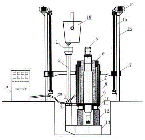
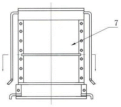
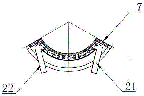
[0059] Embodiment 1: in figure 1 , figure 2 , image 3 , Figure 4 , Figure 5 , Figure 6 Among them, the equipment has a gantry-type regional directional solidification lifting device 16, a lifting platform 17 is installed on the gantry-type regional directional solidification lifting device 6, an electromagnetic induction heater 8 is installed on the lifting platform 17, and the lifting motor 14 rotates and lifts The screw 15 or hydraulic equipment drives the lifting table 17 to move up and down at the set speed, and the electromagnetic induction power control cabinet 19 is installed on the side of the directional solidification lifting equipment 16 in the gantry type area. The two output ends of the electromagnetic induction power control cabinet 19 are cooled by water. The cable 20 is connected to the two ends of the electromagnetic induction heater 8, and there is a base bracket at the bottom of the directional solidification lifting device 16 in the gantry type ar...

Embodiment 2

[0075] Example 2: In figure 1 , figure 2 , image 3 , Figure 4 , Figure 5 , Figure 6 Among them, the equipment has a gantry-type regional directional solidification lifting device 16, a lifting platform 17 is installed on the gantry-type regional directional solidification lifting device 6, an electromagnetic induction heater 8 is installed on the lifting platform 17, and the lifting motor 14 rotates and lifts The screw 15 or hydraulic equipment drives the lifting table 17 to move up and down at the set speed, and the electromagnetic induction power control cabinet 19 is installed on the side of the directional solidification lifting equipment 16 in the gantry type area. The two output ends of the electromagnetic induction power control cabinet 19 are cooled by water. The cable 20 is connected to the two ends of the electromagnetic induction heater 8, and there is a base bracket at the bottom of the directional solidification lifting device 16 in the gantry type area, a...

Embodiment 3

[0091] Example 3: In figure 1 , figure 2 , image 3 , Figure 4 , Figure 5 Among them, the equipment has a gantry-type regional directional solidification lifting device 16, a lifting platform 17 is installed on the gantry-type regional directional solidification lifting device 6, an electromagnetic induction heater 8 is installed on the lifting platform 17, and the lifting motor 14 rotates and lifts The screw 15 or hydraulic equipment drives the lifting table 17 to move up and down at the set speed, and the electromagnetic induction power control cabinet 19 is installed on the side of the directional solidification lifting equipment 16 in the gantry type area. The two output ends of the electromagnetic induction power control cabinet 19 are cooled by water. The cable 20 is connected to the two ends of the electromagnetic induction heater 8, and there is a base bracket at the bottom of the directional solidification lifting device 16 in the gantry type area, and a suppor...


PUM

PropertyMeasurementUnit
thicknessaaaaaaaaaa
tensile strengthaaaaaaaaaa

Abstract

The invention discloses a manufacturing technology and device of a forged steel roller neck alloy nodular cast iron composite roller. The forged steel roller neck alloy nodular cast iron composite roller comprises, by mass percent, 3.2%-3.9% of C, 1.6%-2.1% of Si, 0.4%-0.8% of Mn, not larger than 0.05% of P, not larger than 0.03% of S, 0.2%-0.5% of Cr, 0.3%-0.7% of Mo, 1.4%-2.0% of Ni, 0.04%-0.06% of Mg, 0.06%-0.2% of Nb, 0.1%-0.25% of Ti, 0.2%-0.5% of V, 1.5%-2.5% of Ba, 1%-2% of Ca, 1.0%-2.0% of RE and the balance Fe. Rare-earth nodulizing and Ba, Ca and silicon iron compound inoculation are adopted, and Nb, Ti and V are added for modification, so that the mechanical property of the roller is improved, a forged steel roller neck is adopted to improve the strength of the roller, and an induction heater is adopted to carry out in-mold whole heating casting on a forged steel or cast steel core stick; and a combined type water cooled crystallizer is molded, a lifting device lifts the heater upwards at a certain speed to form area directional solidification, a composite layer interface is dynamically controlled, the technology is simple, the efficiency is high, the electric consumption is small, the cost is low, no composition segregation exists in the composite layer, and the service life of the roller is long.

Description

Technical field [0001] The present invention is a metal pressure processing technology field, which specializes in the manufacturing process and equipment of a forged steel roller neck alloy cylinder ink cast iron. It is suitable for the manufacturing of composite rolls in the steel rolling industry. Background technique [0002] Rolls are known as the "Mother of Steel". It is a tool for metal materials to produce plastic deformation in metal pressure extension of steel, aluminum, copper and other metal pressure extensions.Rolling the indispensable key components and the most important community consumption components, the cost of consumption is about 5%to 15%of the cost of rolling production.If you consider factors such as production shutdown, property reduction and increased equipment maintenance caused by roll consumption, the proportion of production costs will be higher. [0003] The rolling machine is an important equipment in metal pressure processing and production, and i...

Claims


Application Information

Patent Timeline
Patent Type & Authority Applications(China)
IPC IPC(8): B22D19/16B22D11/049C22C37/10C22C37/04
Inventor 丁家伟丁刚耿德英鹿微微鹿策施孟达孔军
Owner 丹阳恒庆复合材料科技有限公司
Why Eureka
Try Eureka