Harmless treatment method and harmless treatment device for industrial petroleum wastes

A technology of harmless treatment and petroleum industry, applied in the direction of chemical instruments and methods, solid waste removal, transportation and packaging, etc., can solve the problems of unsuitable on-site treatment, large occupation area, large water consumption, etc., to achieve The treatment product is completely harmless, low energy consumption and good operability

Inactive Publication Date: 2016-03-23
BEIJING UPC ENERGY TECH SERVICE CO LTD
View PDF8 Cites 14 Cited by
  • Summary
  • Abstract
  • Description
  • Claims
  • Application Information

AI Technical Summary

Problems solved by technology

The defect of this technology is: 1, this method will consume a large amount of water resources, and an average well will consume 3-20 ten thousand cubic meters of water; 3. This method only transfers the pollution source, which may cause potential hazards to the groundwater system and may induce geological disasters
The disadvantages of this technology are: 1. The occupation time is too long, generally 5-7 days, and the elder can reach 20 days; %; but for other polymer substances can not be degraded
[0010] 1. The processing cost is high; for example, the high-efficiency curing agent used in the drilling cuttings reinjection method and curing method has a high cost problem;
[0011] 2. Produce other pollution; for example, the incineration method requires incineration equipment, the investment cost is high, and toxic and harmful substances will be released during incineration, which will cause secondary pollution;
[0012] 3. The oil removal rate is low; it is far from the "zero discharge standard";
[0013] 4. The treatment cycle is long and the area is large, so it is not suitable for on-site treatment; such as biological treatment, etc.

Method used


Image

  • Harmless treatment method and harmless treatment device for industrial petroleum wastes
  • Harmless treatment method and harmless treatment device for industrial petroleum wastes
  • Harmless treatment method and harmless treatment device for industrial petroleum wastes

Examples


Embodiment 1

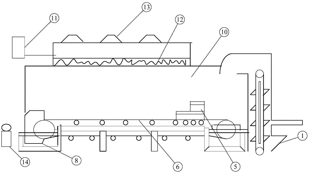
[0074] This embodiment provides a device for harmless treatment of petroleum industrial waste, wherein the device includes

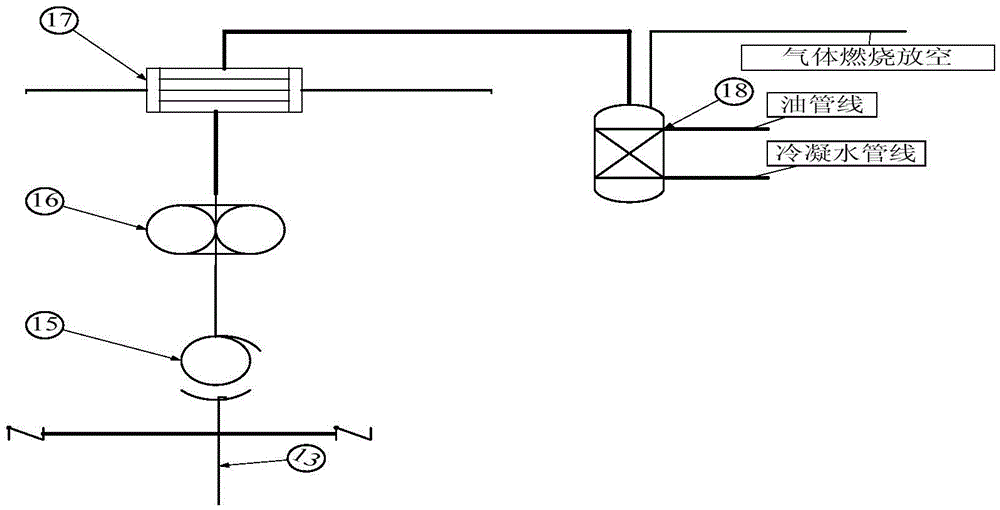
[0075] Bucket elevator 1, feeding hopper 5, microwave device, conveying device with conveyor belt 6, solid waste storage tank 14, filtering device 15, gas compressing device 16, condensing device 17 and oil-gas-water three-phase separation device 18;

[0076] The microwave device includes a microwave heating box 10, a microwave conduit 12 and a microwave source 11; the microwave conduit 12 and the microwave source 11 are located on the upper surface of the microwave heating box 10, and the microwave source 11 is located at the microwave conduit 12 and the microwave heating box Between 10; the microwave device is provided with an exhaust port 13 for discharging the gas generated during the pyrolysis process of petroleum industrial waste out of the microwave heating box;

[0077] The bucket elevator 1 is a bucket elevator 1 for adding oil industry waste to...

Embodiment 2

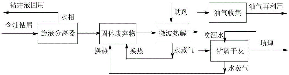
[0088] This embodiment provides a method for harmless treatment of petroleum industrial waste, which is realized by using the device for harmless treatment of petroleum industrial waste provided in Example 1 above, which includes the following steps:

[0089] During the development of onshore oilfields, the mud pump is 0.25m 3 The / h feed rate is transported into the two-stage series solid control separator, and the clear liquid from the second stage is collected and used as the liquid in the oilfield development process to continue to be recycled and reused. Collect the sludge solid waste separated by the secondary solid control separator. The sludge solid waste contains 27% water, 21% oil and 52% solid content. Add 5% petroleum coke additive, stir well to form the sludge solid mixture; use the bucket elevator 1 to add the sludge solid mixture into the hopper 5, then spread the sludge solid mixture evenly on the conveyor belt 6 along with the movement of the conveyor belt 6, ...

Embodiment 3

[0093] This embodiment provides a method for harmless treatment of petroleum industrial waste, which is realized by using the device for harmless treatment of petroleum industrial waste provided in Example 1 above, which includes the following steps:

[0094] During the drilling and development of offshore oilfields, mud pumps are used to pump 0.5m 3 / h feed rate is transported into the three-stage solid control separator in series, and the clear liquid from the third stage is collected and used as the liquid in the oilfield development process to continue to be recycled and reused. Collect the concentrated oily sludge solid waste separated by the three-stage solid control separator. The concentrated oily sludge solid waste contains 24% water, 12% oil, and 64% drilling cuttings. Add 15% petroleum coke additive, stir to form the sludge solid mixture; use the bucket elevator 1 to add the sludge solid mixture into the hopper 5, and then spread the sludge solid mixture evenly on t...


PUM


Abstract

The invention provides a harmless treatment method and a harmless treatment device for industrial petroleum wastes. The method comprises the following steps: performing microwave heating treatment by taking industrial petroleum wastes or pre-treated industrial petroleum wastes as a microwave pyrolytic raw material; heating to a temperature of 500 to 1400 DEG C; controlling the temperature increment speed in a temperature increasing process in which the material is heated to the temperature of 350 to 400 DEG C to be 10 to 50DEG C / min; controlling the microwave treatment time after the material is heated to the temperature of 350 to 400 DEG C to be 5min to 30min; carbonizing and pyrolyzing the raw material into a gas phase part and a solid phase part during the microwave heating process, and respectively recycling the gas phase part and the solid phase part. The invention also provides the harmless treatment device for the industrial petroleum wastes. In the method provided by the invention, heat energy can be fully utilized; energy consumption is relatively low; the method has the advantages of good operability, stable system, low cost, totally-harmless treatment products and the like.

Description

technical field [0001] The invention relates to a method and device for harmless treatment of petroleum industrial waste, belonging to the technical field of petroleum industrial waste treatment. Background technique [0002] In the process of oil field exploration and development, it is inevitable to produce a large amount of mixtures containing oil, water, bentonite, sediment, petroleum additives and drilling cuttings (hereinafter referred to as petroleum industrial waste), which contain a large amount of Mineral oil, high molecular polymers, phenolic compounds, heavy metals and other toxic substances, especially the organic substances in them, if they are directly discharged, they will pollute the soil, surface and groundwater, which can directly or indirectly affect plants, animals and Hazard to human health. Therefore, the oil industry waste must first be harmlessly treated so that it meets the national emission standards before it is discharged, otherwise it will caus...

Claims


Application Information

Patent Timeline
Patent Type & Authority Applications(China)
IPC IPC(8): B09B3/00
CPCB09B3/40
Inventor 不公告发明人
Owner BEIJING UPC ENERGY TECH SERVICE CO LTD
Why Eureka
Try Eureka