Active temperature field regulating and controlling system for manufacturing high-energy beam reinforced material and control method for active temperature field regulating and controlling system

A technology of additive manufacturing and control system, which is applied in three-dimensional, high-energy beam additive manufacturing and its heat treatment, partitioned gradient temperature field active control system and its control field, which can solve the problems of non-free adjustment and reduce the occupation time , shorten the heat treatment cycle, and save energy

Active Publication Date: 2016-04-20
HUAZHONG UNIV OF SCI & TECH
View PDF5 Cites 85 Cited by
  • Summary
  • Abstract
  • Description
  • Claims
  • Application Information

AI Technical Summary

Problems solved by technology

[0005] In view of the above problems, in order to overcome the shortcomings of the traditional temperature field control system that cannot be adjusted freely, realize the temperature gradient control of the Z direction and the XOY plane during the p

Method used


Image

  • Active temperature field regulating and controlling system for manufacturing high-energy beam reinforced material and control method for active temperature field regulating and controlling system
  • Active temperature field regulating and controlling system for manufacturing high-energy beam reinforced material and control method for active temperature field regulating and controlling system
  • Active temperature field regulating and controlling system for manufacturing high-energy beam reinforced material and control method for active temperature field regulating and controlling system

Examples


Embodiment 1

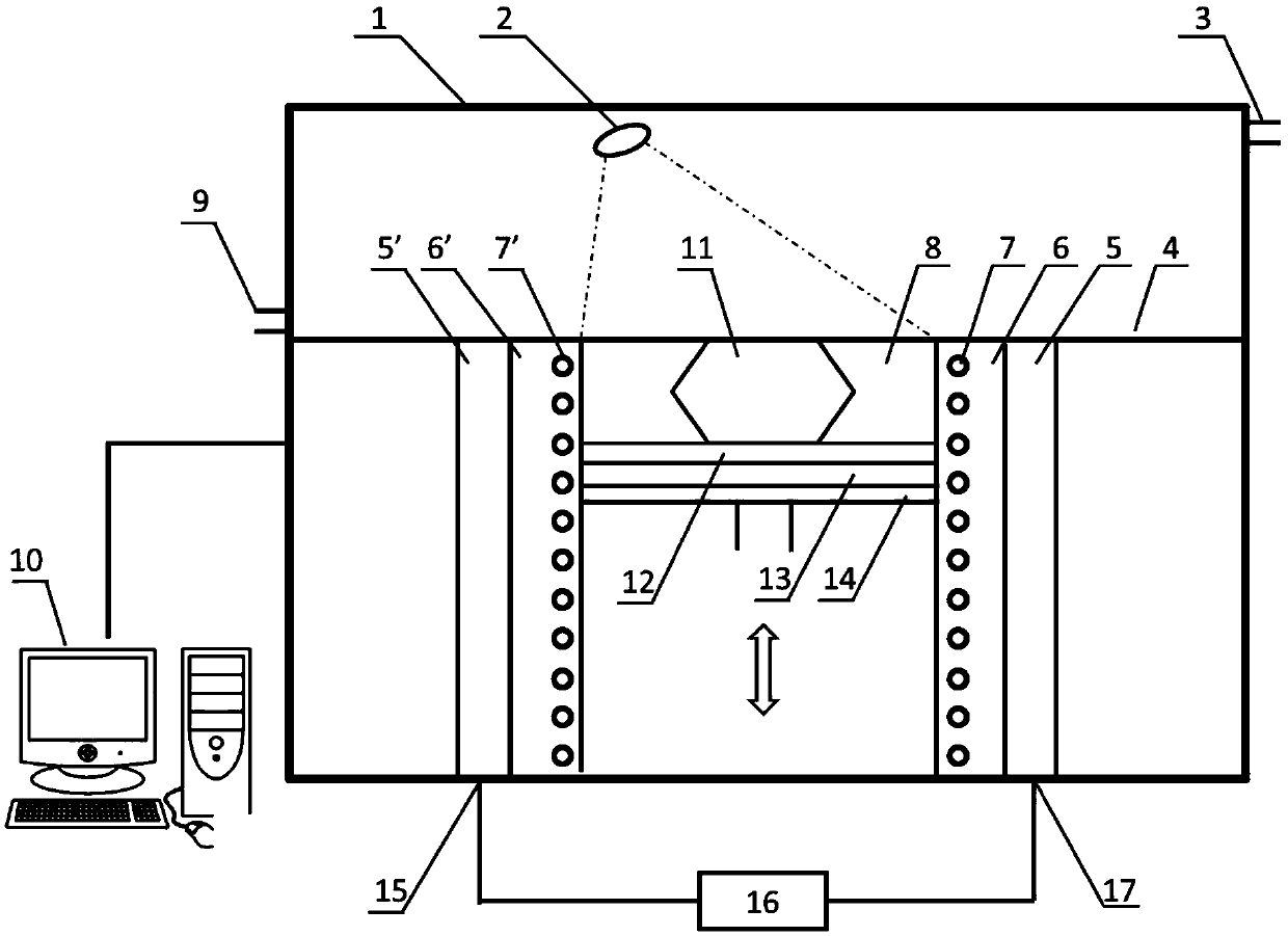
[0060] The structure of this example is as follows figure 1 As shown, taking laser rapid prototyping as an example, the infrared camera 2 and temperature measuring thermocouple are used simultaneously to monitor the temperature field, as shown in Figure 7 As shown, the control system 10 synchronously completes parts processing, temperature measurement and temperature control, and the specific workflow is as follows:

[0061] (1) Installation and leveling of the substrate 12: fix the substrate 12 after sandblasting on the bottom surface heating system 13 through positioning screws, use a dial gauge to keep the upper surface of the substrate 12 level and ensure that the upper surface of the substrate 12 is at the same level as the workbench 4. on a horizontal plane;

[0062] (2) Establish a protective atmosphere: manually close the cavity 1, connect the protective gas source (nitrogen, argon, helium, or a mixture of the above gases, etc.) to the gas inlet 9, and open the gas o...

Embodiment 2

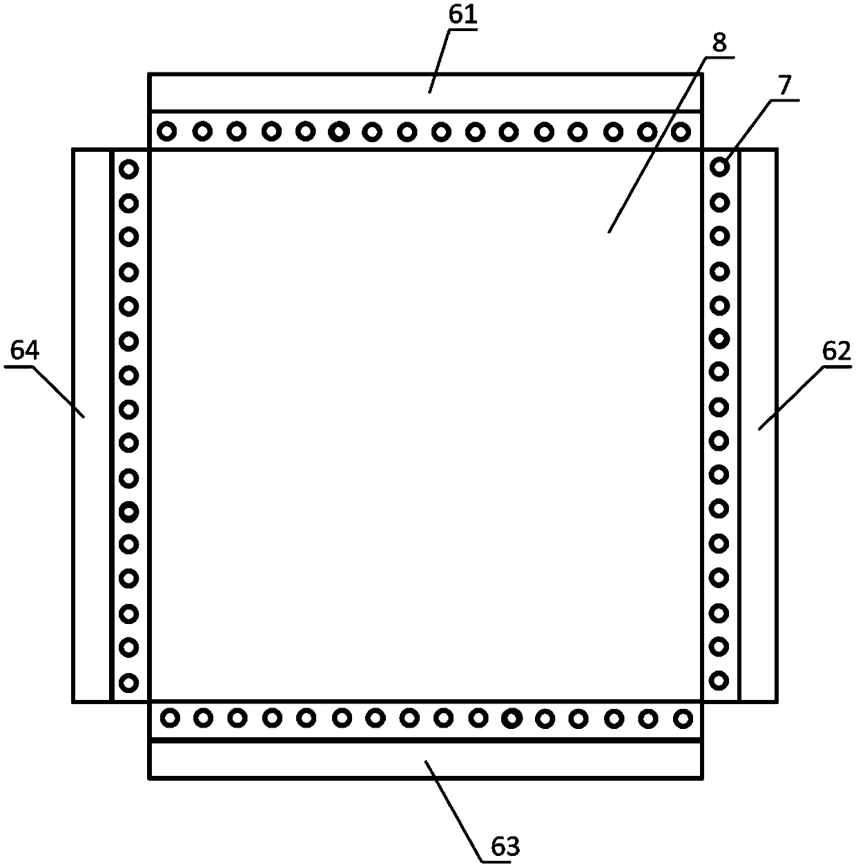
[0071] The structure used in this example is as follows Figure 8 As shown, taking laser rapid prototyping as an example, only infrared cameras are used for temperature field monitoring, and the specific workflow refers to that in Example 1 Figure 7 shown. The difference is that during the forming process, only the infrared camera 2 is used to monitor the temperature of the temperature field without turning on the temperature measuring thermocouple 7 . It should be noted that in this embodiment, since the temperature measuring thermocouple 7 is not turned on, the temperature field adjustment on the XOZ and YOZ planes during the forming process is only controlled by the control system 10 to control the set temperature of the side heating system 6 . For example, when the position of the substrate 12 drops to the position of the side heating module 6-p, set the corresponding side heating system 6-1~6-p temperature rise temperature as T 2 , set the side heating system 6-(p+1) h...

Embodiment 3

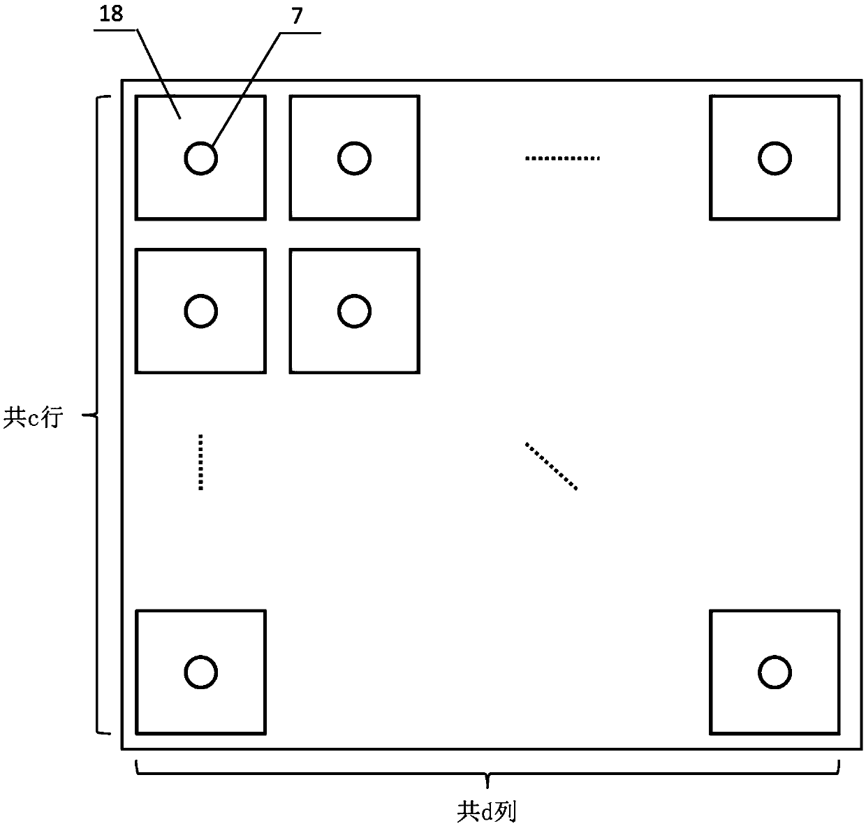
[0073] The structure used in this example is as follows Figure 9 As shown, taking laser rapid prototyping as an example, only the temperature measuring thermocouple 7 is used to monitor the temperature field. For the specific workflow, refer to the Figure 7 shown. The difference is that during the forming process, the temperature field is only monitored by the temperature measuring thermocouple 7 without turning on the infrared camera 2 . It should be noted that in this embodiment, since the infrared camera 2 is not turned on, the temperature field adjustment on the XOY plane during the forming process is only controlled by the control system 10 to control the set temperature of the bottom surface heating system 13 . For example, according to the XOY plane projection diagram of the component to be processed, the bottom surface heating system 13 is turned on, and the bottom surface heating sub-module 22 corresponding to the projection diagram is opened synchronously, and the...


PUM


Abstract

The invention discloses an active gradient temperature field regulating and controlling system and a control method thereof. The system is composed of a temperature field monitoring system, a heating system and a control system, wherein the temperature field monitoring system is used for measuring temperature field information on an XOY plane and at the periphery of a forming region and feeding the temperature field information back to the control system after quantitatively processing the temperature field information; and the heating system is used for independently regulating subregions of a temperature field at the bottom and periphery of a forming tank in real time according to a command of the control system so as to keep the temperature field of the whole machining region constant in the machining process, keep a processed region and an unprocessed region in a reasonable temperature gradient and avoid structural member warping, deforming and cracking caused by thermal stresses. The system can also be used for directly carrying out stress relief annealing on a formed structural member or directly carrying out stress relief on the formed structural member while machining, so that the problems of warping, deforming, cracking and the like easily caused in the forming process are effectively solved, not only is the time shortened, but also energy sources are saved, meanwhile, the holding time of equipment can be effectively shortened, and the utilization ratio of the equipment can be increased.

Description

technical field [0001] The invention belongs to the technical field of high-energy beam additive manufacturing, and specifically relates to a three-dimensional, partitioned gradient temperature field active control system and a control method thereof. The invention is particularly suitable for high-energy beam additive manufacturing and heat treatment, and is also suitable for other processing equipment that requires temperature gradient regulation. Background technique [0002] Compared with the traditional removal-cutting method, additive manufacturing technology is a method based on the "discrete-stacking" principle of "bottom-up, layer-by-layer increase" driven by the three-dimensional data of the part to directly manufacture the required parts. On this basis, metal additive manufacturing technology uses high-energy beams (laser beams, electron beams, plasma or ion beams) as heat sources to heat materials to combine them (sintering or melting), and directly manufacture p...

Claims


Application Information

Patent Timeline
IPC IPC(8): B22F3/105B33Y50/02
CPCB22F10/00B22F10/32B22F10/368B22F12/90B22F10/28B22F12/17B22F12/20B22F10/50Y02P10/25
Inventor 王泽敏李方志曾晓雁
Owner HUAZHONG UNIV OF SCI & TECH
Why Eureka
Try Eureka