
Die plasma cladding direct remanufacturing equipment and remanufacturing method

A plasma cladding and remanufacturing technology, which is applied in the field of plasma cladding direct remanufacturing equipment and remanufacturing, can solve the problems of large machining allowance, high consumption of surfacing materials, and high cost of mold materials

Inactive Publication Date: 2016-06-22
SINOADDITIVE MFG EQUIP CO LTD
View PDF23 Cites 1 Cited by
  • Summary
  • Abstract
  • Description
  • Claims
  • Application Information

AI Technical Summary

Problems solved by technology

[0006] First, laser cladding equipment is expensive. At the same time, due to the short life, high price, high replacement and maintenance costs of the laser system of the core device of the equipment, the cost of remanufacturing molds by laser cladding is very high;
[0007] Second, the mechanical properties of the mold are very demanding. In order to achieve good performance after laser cladding, the metal powder is required to have good fluidity. Generally, spherical metal powder should be used, resulting in high material costs for laser cladding and remanufacturing molds;
[0011] First, surfacing remanufacturing molds generally require preheating and tempering heat treatment due to high local heat input and poor process controllability. At the same time, it is difficult to surfacing welding with materials whose mechanical properties exceed the mold material itself, resulting in surfacing remanufacturing molds Complex process and poor performance;
[0012] Second, the surface roughness of the surfacing remanufacturing mold is high, especially some molds need to be surfacing to fill the mold cavity, and finally process and shape, the consumption of surfacing materials is too high, the cost is high, and the processing allowance is large
But at present, there are three main problems in the selective electron beam rapid prototyping technology: first, the electron beam rapid prototyping technology needs a vacuum environment to form the energy source electron beam and avoid the oxidation of metal parts during the forming process
This makes the structure of the electron beam rapid prototyping equipment complex, the size of the molded parts is limited, and the molding equipment is expensive; second, the electron beam rapid prototyping technology requires a powder spreading system or a molding material supply system
This makes the structure of the electron beam rapid prototyping equipment complex, not only the size of the formed parts is limited, but also the forming efficiency is low; third, in order to ensure the mechanical properties of the parts, the electron beam rapid prototyping technology requires spherical metal powder with good fluidity
This makes SLM rapid prototyping equipment expensive to run

Method used


Image

  • Die plasma cladding direct remanufacturing equipment and remanufacturing method
  • Die plasma cladding direct remanufacturing equipment and remanufacturing method
  • Die plasma cladding direct remanufacturing equipment and remanufacturing method

Examples


Embodiment 1

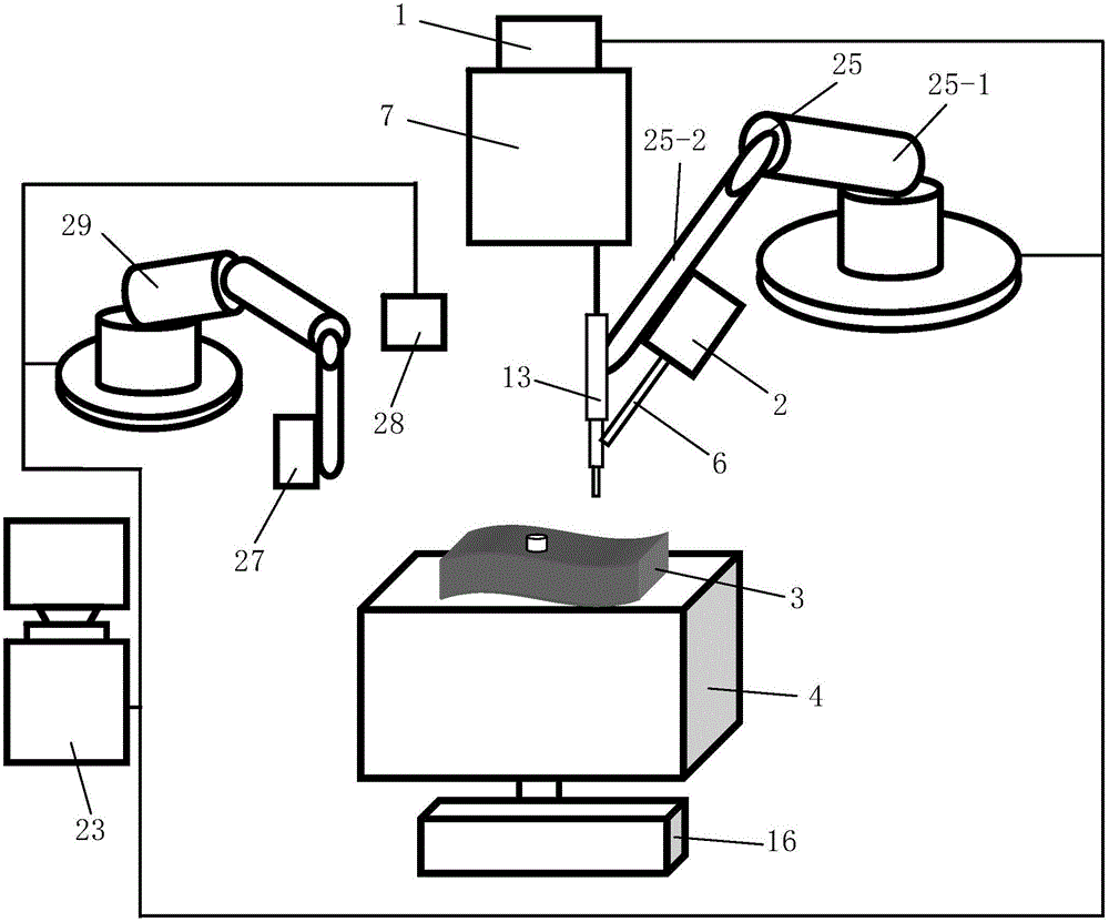
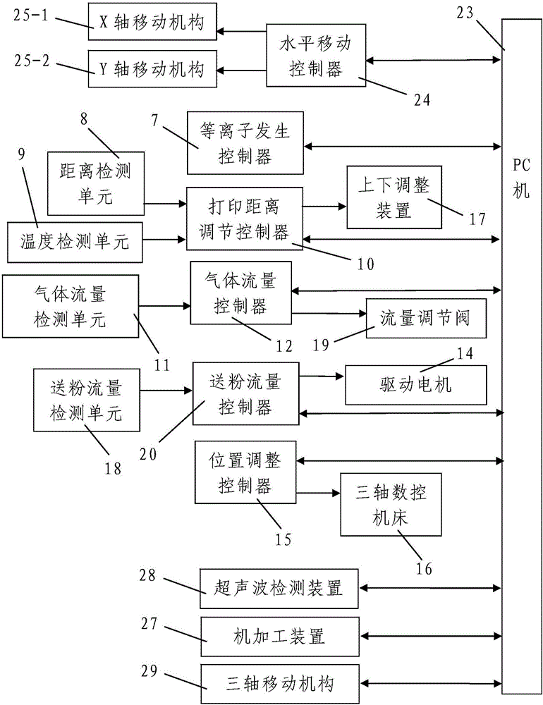
[0110] Such as figure 1 A mold plasma cladding direct remanufacturing equipment shown is characterized in that it consists of a monitoring system, a plasma beam processing system, a machining device 27 for machining the mold 3 to be repaired, and a horizontal printing machine for placing the mold 3 to be repaired. The platform 4 is composed of a temporary fixture for temporarily fixing the mold 3 to be repaired; the machining device 27 is located above the horizontal printing platform 4; the temporary fixing piece is arranged on the horizontal printing platform 4.

[0111] The plasma beam processing system consists of a plasma generator equipped with a shower head and used to generate a plasma beam, a gas supply device 1 for supplying working gas to the plasma generator, and a gas supply device 1 for continuously generating plasma beams to the plasma generator. It consists of a powder feeding device for sending printing materials into the plasma beam and a printing position ad...

Embodiment 2

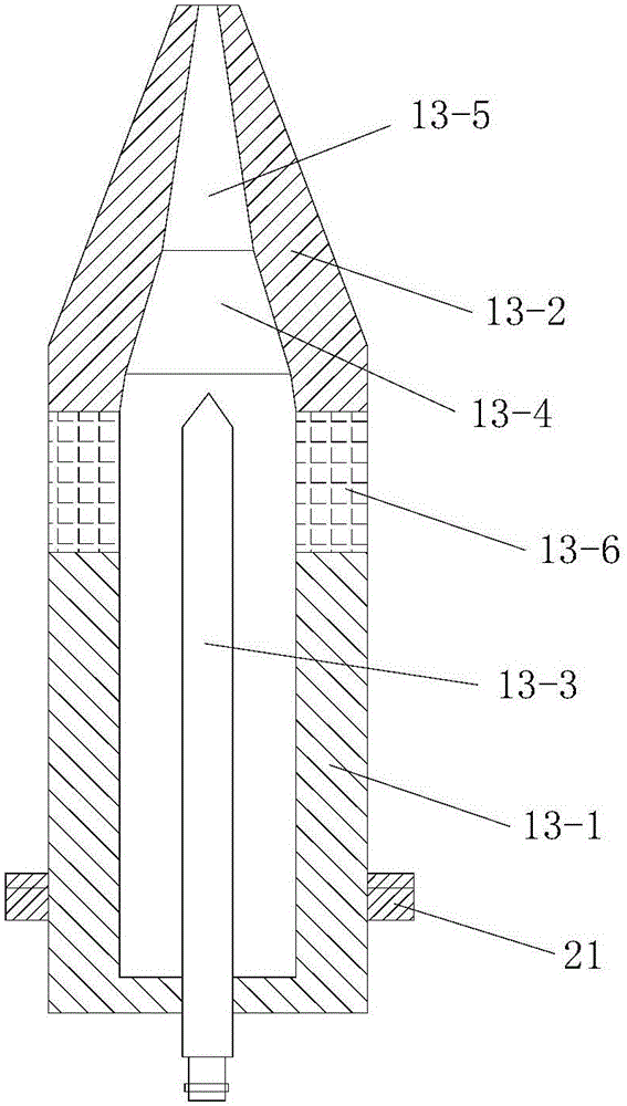
[0236] In this example, if Figure 7 As shown, the difference between the mold plasma cladding direct remanufacturing equipment used and the embodiment 1 is that the angle between the nozzle 13-5 and the central axis of the gun body 13-1 is 30°-45°.

[0237] In this way, after changing the direction of the plasma beam through the nozzle 13-5, the thermal load impact of the plasma jet on the anode nozzle 13-2 can be effectively reduced, and the anode ablation condition is improved.

[0238] In this embodiment, the structure, connection relationship and working principle of the remaining parts of the mold plasma cladding direct remanufacturing equipment are the same as those in Embodiment 1.

[0239] In this embodiment, the direct remanufacturing method of the mold by plasma cladding is the same as that in Embodiment 1.


PUM


Abstract

The invention discloses die plasma cladding direct remanufacturing equipment and a remanufacturing method. The equipment is composed of a monitoring system, a plasma beam machining system, a machining device for conducting machining on a to-be-repaired die, a horizontal printing table for containing the to-be-repaired die and a temporary fixing piece for conducting temporary fixing on the to-be-repaired die; the plasma beam machining system is composed of a plasma generator, an air supply device, a powder feeding device and a printing position adjusting device; and the monitoring system comprises a horizontal movement controller, a temperature detecting unit, a distance detecting unit, a printing distance adjusting controller and a rotation controller, and a temperature regulation and control unit is composed of the temperature detecting unit and the printing distance adjusting controller. The remanufacturing method includes the steps of (1) die defect detection and (2) die repairing. The die plasma cladding direct remanufacturing equipment is reasonable in design, easy and convenient to operate, high in efficiency, good in using effect and free of sealing a molding chamber, the repairing process is directly executed under the atmospheric environment, and the quality of the repaired die is good.

Description

technical field [0001] The invention belongs to the technical field of rapid prototyping, and in particular relates to a mold plasma cladding direct remanufacturing equipment and a remanufacturing method. Background technique [0002] Mold refers to various molds and tools used in industrial production for injection molding, blow molding, extrusion, die-casting or forging forming, smelting, stamping and other methods to obtain the required products. In short, a mold is a tool used to shape a product. The molding surface of the mold refers to the surface used to shape the product (also called the product), and the molding surface is the surface that directly contacts the molded product. Wherein, the molding surface of the cavity refers to the outer surface for molding the product, and the molding surface of the core is the inner surface for molding the product. The processing quality, processing accuracy and performance of the molding surface of the mold are required to be ...

Claims


Application Information

Patent Timeline
Patent Type & Authority Applications(China)
IPC IPC(8): B22F3/105B33Y30/00B33Y10/00B22F5/00
CPCB22F5/007B33Y10/00B33Y30/00B22F10/00B22F10/322B22F10/22B22F12/90B22F12/53B22F10/80B22F12/224Y02P10/25
Inventor 华云峰程国君郝勇魏志宇
Owner SINOADDITIVE MFG EQUIP CO LTD
Learn More