Transparent conducting layer manufacturing method for increasing light emitting diode chip brightness
A technology of light-emitting diodes and transparent conductive layers, applied in circuits, electrical components, semiconductor devices, etc., can solve the problem that light cannot be used to improve light efficiency, and achieve the effect of increasing the output rate and improving the luminous efficiency.
- Summary
- Abstract
- Description
- Claims
- Application Information
AI Technical Summary
Problems solved by technology
Method used
Image
Examples
Embodiment 1
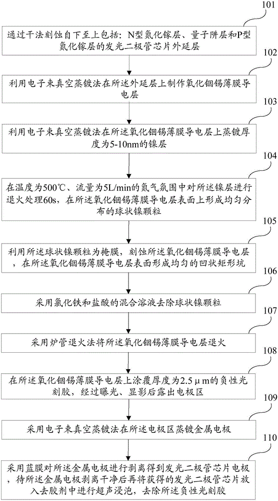
[0057] Such as figure 1 As shown in FIG. 2 , it is a schematic flowchart of an alternative embodiment of the method for manufacturing a transparent conductive layer for improving the brightness of a light-emitting diode chip according to the present invention. In the present invention, the surface of the ITO film layer of the light-emitting diode chip is made into a nano-scale concavo-convex shape, which is beneficial to the light emission inside the light-emitting diode chip, thereby improving the luminous efficiency of the light-emitting diode chip. The manufacturing method of the transparent conductive layer for improving the brightness of the light-emitting diode chip described in this embodiment includes the following steps:
[0058] Step 101, dry etching the epitaxial layer of the light emitting diode chip including: N-type GaN layer, quantum well layer and P-type GaN layer from bottom to top.
[0059] Step 102, using an electron beam vacuum evaporation method to form a...
Embodiment 2
[0072] Such as Figure 7 as shown, Figure 7 It is a schematic flowchart of the method for manufacturing a transparent conductive layer for improving the brightness of a light-emitting diode chip described in Embodiment 2 of the present invention. In this embodiment, a specific method for making the concave-convex structure on the surface of the ITO layer is provided. The manufacturing method of the transparent conductive layer for improving the brightness of the light-emitting diode chip in this embodiment includes the following steps:
[0073] Step 701, dry etching the epitaxial layer of the LED chip including: N-type GaN layer, quantum well layer and P-type GaN layer from bottom to top.
[0074] Preferably, in this step, the N-type gallium nitride layer, the quantum well layer and the epitaxial layer of the P-type gallium nitride layer of the light-emitting diode chip are formed from bottom to top with an etching depth of 1 μm and a width of the scribe line between 8-14 μ...
Embodiment 3
[0091] Such as Figure 8 As shown, it is a schematic flowchart of a specific embodiment of the manufacturing method of the transparent conductive layer for improving the brightness of the light-emitting diode chip disclosed in this embodiment. The manufacturing method of the transparent conductive layer for improving the brightness of the light-emitting diode chip in this embodiment includes the following steps:
[0092]Step 801, dry etching the epitaxial layer of the N-type GaN layer, the quantum well layer and the P-type GaN layer of the light-emitting diode chip with an etching depth of 1 μm and a dicing line width of 10 μm from bottom to top, forming step and expose the N-type gallium nitride layer.
[0093] Step 802, under the conditions of a chamber temperature of 160°C, an oxygen flow rate of 10 sccm, and a vacuum degree of 3×10⁻⁵ Torr, an indium tin oxide thin film conductive layer is formed on the epitaxial layer by electron beam vacuum evaporation, wherein the The ...
PUM
| Property | Measurement | Unit |
|---|---|---|
| thickness | aaaaa | aaaaa |
| thickness | aaaaa | aaaaa |
Abstract
Description
Claims
Application Information
 - R&D
- Intellectual Property
- Life Sciences
- Materials
- Tech Scout
- Unparalleled Data Quality
- Higher Quality Content
- 60% Fewer Hallucinations
Browse by: Latest US Patents, China's latest patents, Technical Efficacy Thesaurus, Application Domain, Technology Topic, Popular Technical Reports.
© 2025 PatSnap. All rights reserved.Legal|Privacy policy|Modern Slavery Act Transparency Statement|Sitemap|About US| Contact US: help@patsnap.com


