Coal pyrolysis and cracking gas production combined gas power generation system

A technology of pyrolysis gas and pyrolysis, which is applied in gas fuel, fuel, petroleum industry, etc., can solve the problems of large condensation recovery system, many operation links, low gas calorific value, etc., to save construction cost, floor space, temperature, etc. Evenly distributed, clean and efficient use of the effect

Inactive Publication Date: 2016-08-10
SHENWU TECH GRP CO LTD
View PDF6 Cites 2 Cited by
  • Summary
  • Abstract
  • Description
  • Claims
  • Application Information

AI Technical Summary

Problems solved by technology

The thermal efficiency of the external heat type is low, and the secondary decomposition of volatile products is serious; the internal heat type process overcomes the shortcomings of the external heat type, and transfers heat to the coal by means of heat carriers (solid heat carrier and gas heat carrier)
The gas heat carrier process has the disadvantages of distilled dry distillation gas, large condensation recovery system, low calorific value of gas, and difficulty in further comprehensive utilization
The solid heat carrier process has certain advantages relatively speaking, but there are many disadvantages such as complex process operation links and high manufacturing costs.
The main purpose of the existing pyrolysis furnaces is to produce oil products, but most of the pyrolysis furnaces, especially those that use pulverized coal as raw materials, contain a lot of dust in the pyrolysis oil, which makes it difficult to effectively process the pyrolysis oil. Utilization, the value of pyrolysis oil is not high, etc.

Method used


Image

  • Coal pyrolysis and cracking gas production combined gas power generation system
  • Coal pyrolysis and cracking gas production combined gas power generation system
  • Coal pyrolysis and cracking gas production combined gas power generation system

Examples


Embodiment 1

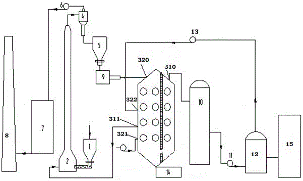
[0055] (1) The granular coal crushed to a particle size of ≤10mm enters the riser dryer 2 through the hopper 1. In the riser dryer, 150-250 The flue gas at ℃ dries and lifts the coal, the coal enters the drying cyclone separator 4, and the separated coal powder enters the pyrolysis hopper 5, and the flue gas at about 70-130 °C is sent to the exhaust gas purification through the exhaust fan 6 Device 7, the flue gas that reaches the discharge standard is discharged through the chimney 8.

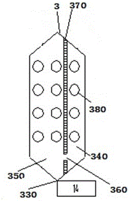
[0056] (2) Coal enters the regenerative moving bed reactor 3 through the star-shaped feeder 9 in the pyrolysis hopper 5, and the moving bed reactor 3 is divided into a pyrolysis chamber and a cracking chamber in a grid pattern.

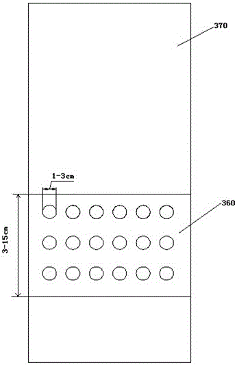
[0057] (3) One-way regenerative radiant tubes are evenly arranged in the pyrolysis chamber, and the temperature of the tube wall is controlled at 500-700°C by a gas regulating valve. The material stays in the reactor from top to bottom for 1-40 minutes, and is heated ...


PUM

PropertyMeasurementUnit
thicknessaaaaaaaaaa
heightaaaaaaaaaa
diameteraaaaaaaaaa

Abstract

The invention provides a coal pyrolysis and cracking gas production combined gas power generation system, which comprises a pyrolysis hopper, a first feeding device, a pyrolysis and cracking reactor, a spraying tower, a gas tank and a generator set, wherein the pyrolysis and cracking reactor comprises a heat insulation brick wall and a communicating component; the internal space of the reactor is divided into a pyrolysis chamber and a cracking chamber by the heat insulation brick wall; the communicating component is arranged at the lower part of the heat insulation brick wall; the spraying tower is connected with a cracking gas outlet; the gas tank is connected with the spraying tower; the generator set is connected with the gas tank. The reactor of the power generation system is divided into the pyrolysis chamber and the cracking chamber, and oil gas generated by the pyrolysis chamber can enter the cracking chamber for deep cracking, so that the problem that produced pyrolitic oil contains dust is solved, and clean and efficient utilization of coal is really implemented. Two kinds of operation can be integrally executed in one furnace body, so that construction cost is reduced, and the occupied area is saved; a small part of pyrolysis gas is supplied to a radiator tube for combustion, and the rest gas enters the gas generator set to be combusted for power generation.

Description

technical field [0001] The invention belongs to the technical field of coal pyrolysis and cracking gas production and gas combustion power generation, and specifically relates to a combined power generation system based on regenerative radiant tube heating particle coal pyrolysis and cracking system to produce combustible gas. Background technique [0002] my country is rich in coal resources, and most of the raw coal is used for direct combustion except for coking and conversion processing. The direct combustion of coal leads to the fact that the oil and gas resources rich in coal have not been fully refined and utilized, and the thermal efficiency of direct combustion is low, which seriously damages the environment. The pyrolysis of coal is to heat coal under an inert atmosphere to produce semi-coke, gas and tar, etc. These products can be used in stages, fully extracting oil and gas resources, and improving the comprehensive utilization efficiency of coal . Coal pyrolys...

Claims


Application Information

Patent Timeline
Patent Type & Authority Applications(China)
IPC IPC(8): C10L3/00
CPCC10L3/00C10L2290/02
Inventor 耿层层陈水渺肖磊薛逊吴道洪
Owner SHENWU TECH GRP CO LTD
Why Eureka
Try Eureka