Integrated treatment method for malodorous VOCs gas of refining devices

A gas and refining technology, which is applied in the field of integrated treatment of malodorous VOCs gas in refining and chemical equipment, can solve the problems of ineffective treatment of VOCs odorous gas, catalyst deactivation in catalytic oxidation process, and inability to effectively remove organic components, etc., to achieve Low equipment investment and operating costs, reduced operating costs, and reduced usage

Inactive Publication Date: 2016-08-10
JIANGSU NEW CENTURY JIANGNAN ENVIRONMENTAL PROTECTION
View PDF13 Cites 48 Cited by
  • Summary
  • Abstract
  • Description
  • Claims
  • Application Information

AI Technical Summary

Problems solved by technology

The alkaline washing process currently used can only remove H 2 Sulfur-containing compounds such as S cannot effectively remove organic components and generate new waste; due to the large number of sources, multiple treatment systems need to be set up, and the investment and operation costs are high; the direct incineration process only converts H 2 S converted to SO 2 , while not solving SO 2 Pollution issues; high concentrations of sulfur in malodorous gases can deactivate catalytic oxidation process catalysts
In summary, none of the current methods can effectively treat VOCs malodorous gases

Method used


Image

  • Integrated treatment method for malodorous VOCs gas of refining devices
  • Integrated treatment method for malodorous VOCs gas of refining devices

Examples


Embodiment 1

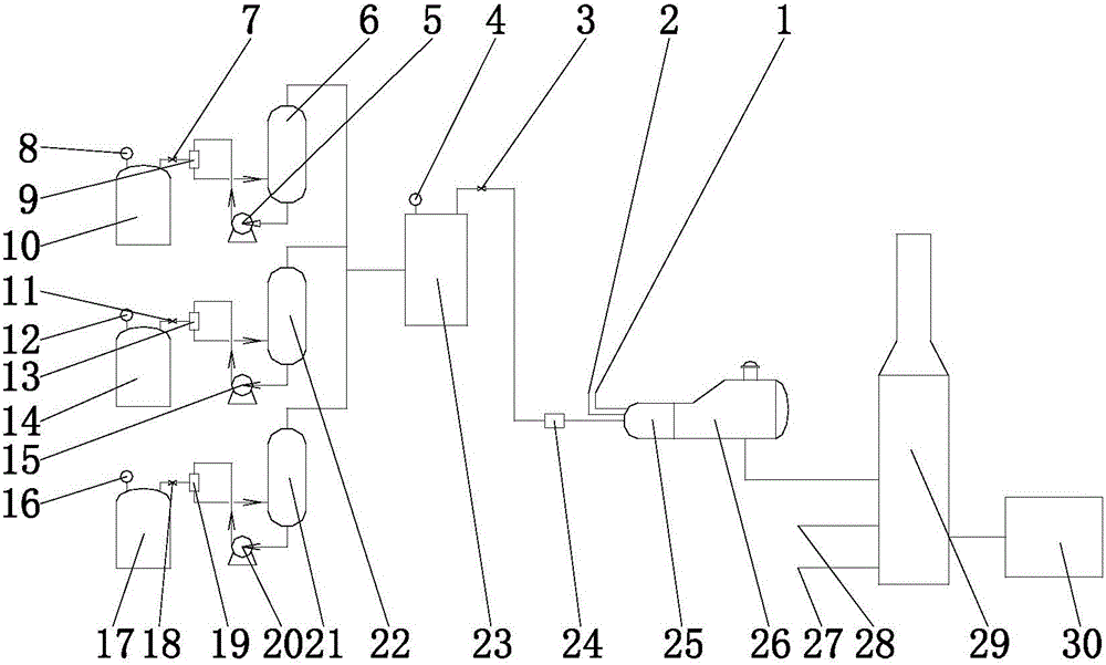
[0028] The acid water tank, intermediate product tank and residual oil tank of a refining unit shall be figure 1 Process construction VOCs treatment system, the volume of the three storage tanks is 5000m 3 , and the pressure is controlled to 15kPag. Acid water tank discharge 150Nm 3 / h malodorous gas, where H 2 S concentration is 42100mg / Nm 3 , the total non-methane hydrocarbon concentration is 41300mg / Nm 3 (calculated as methane); 200Nm of malodorous gas discharged from the residue oil tank 3 / h, where H 2 S concentration is 2000mg / Nm 3 , the total non-methane hydrocarbon concentration is 38000mgN / m 3 ;The odorous gas discharged from the intermediate product tank is 200Nm 3 / h, where H 2 S concentration is 1270mg / Nm 3 , the total non-methane hydrocarbon concentration is 41600mg / Nm 3 (as methane). After passing through the gas-liquid separation device, the above-mentioned gas is passed into the gas storage buffer tank, and the pressure in the tank is controlled to ...

Embodiment 2

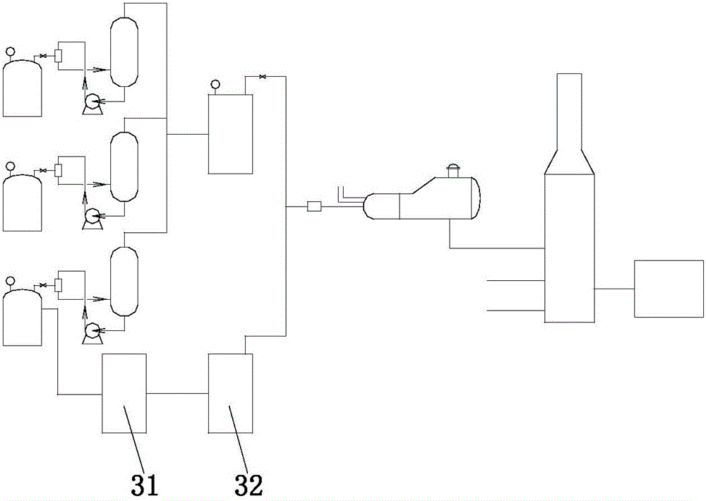
[0030] There are acid water stripping devices, sulfur recovery devices, incineration and waste heat recovery systems and ammonia desulfurization systems in the refinery. figure 2 The shown process builds a VOCs treatment system. The volume of the acid water tank is 4600m 3 , the volume of the intermediate product tank and the residual oil tank is 4800m 3 , the pressure of the three storage tanks are controlled to 14kPa. Acid water tank discharge 120Nm 3 / h malodorous gas, where H 2 S concentration is 31200mg / Nm 3 , the total non-methane hydrocarbon concentration is 28000mg / Nm 3 (calculated as methane); 100Nm of malodorous gas discharged from the residue tank 3 / h, where H 2 S concentration is 800mg / Nm 3 , the total non-methane hydrocarbon concentration is 25000mg / Nm 3 (in terms of methane); 165Nm of malodorous gas discharged from the intermediate product tank 3 / h, where H 2 S concentration is 650mg / Nm 3 , the total non-methane hydrocarbon concentration is 22600mg...


PUM


Abstract

The invention discloses an integrated treatment method for unorganized emission of malodorous VOCs gas from refining and chemical equipment, which collects VOCs gas emitted from refining and chemical storage tanks including residual oil tanks, intermediate product tanks, and acid water tanks. The VOCs gas outlet of the tank is connected to the injection fluid inlet of the liquid jet vacuum pump; the working fluid inlet of the liquid jet vacuum pump is connected to the outlet of the circulation pump, and the mixed fluid outlet is connected to the gas-liquid separation tank; the inlet of the circulation pump is connected to the The liquid outlet of the gas-liquid separation device is connected; the gas outlet of the gas-liquid separation device is connected with the buffer tank; the inlet of the incineration unit is also fed with combustion-supporting gas and air in addition to the VOCs gas in the gas storage buffer tank. , VOCs gas and malodorous gas are incinerated in the incineration unit, and the incineration temperature is 800-1000°C.

Description

technical field [0001] The invention belongs to the technical field of environmental protection, and relates to a method for treating VOCs gas, in particular to an integrated treatment method for malodorous VOCs gas in a refining plant. Background technique [0002] VOCs is a general term for volatile organic compounds with a melting point lower than room temperature and a boiling point range of 50 to 260 °C, mainly including hydrocarbons, aromatic hydrocarbons, alcohols, aldehydes, ketones, lipids, amines and organic acids, etc. , has the characteristics of strong volatility, special odor, irritation and toxicity, which will not only adversely affect the ecological environment, but also cause serious harm to human health. The petroleum refining and petrochemical industries are the main industrial emission sources of VOCs gas. There are many links such as process waste gas emission, leakage of production equipment sealing points, volatilization of storage tanks and loading a...

Claims


Application Information

Patent Timeline
Patent Type & Authority Applications(China)
IPC IPC(8): F23G7/06B01D53/74B01D53/50
CPCF23G7/065B01D53/50B01D53/74
Inventor 罗静张军黄海李静媛
Owner JIANGSU NEW CENTURY JIANGNAN ENVIRONMENTAL PROTECTION
Why Eureka
Try Eureka