

Multi-stage magnetic field arc ion plating method for lining positive bias straight pipe
An arc ion plating and positive bias technology, applied in the field of material surface treatment, can solve problems such as large particle defects and low arc plasma transmission efficiency, improve crystal structure and stress state, avoid large particle defects, and improve bonding strength. Effect
- Summary
- Abstract
- Description
- Claims
- Application Information
AI Technical Summary
Problems solved by technology
Method used
Image

Examples
specific Embodiment approach 1
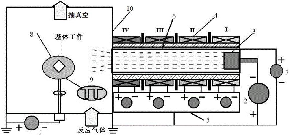
[0015] Specific implementation mode one: the following combination figure 1 Description of this embodiment, the device used in the multi-stage magnetic field arc ion plating method of the lined positive bias straight pipe in this embodiment includes a bias power supply 1, an arc power supply 2, an arc ion plating target source 3, a multi-stage magnetic field device 4, a multiple Level magnetic field power supply 5, lined positive bias straight tube device 6, positive bias power supply 7, sample stage 8, bias power supply waveform oscilloscope 9 and vacuum chamber 10;
[0016] The method includes the following steps:
[0017] Step 1, place the substrate workpiece to be processed on the sample stage 8 in the vacuum chamber 10, connect the workpiece to the output end of the bias power supply 1, and connect the arc ion plating target source 3 installed on the vacuum chamber 10 to the output end of the arc power supply 2 1. The magnetic fields at all levels of the multi-stage magn...
specific Embodiment approach 2
[0026] Embodiment 2: The difference between this embodiment and Embodiment 1 is that the method also includes:
[0027] Step 3: Thin films can be deposited by combining traditional DC magnetron sputtering, pulsed magnetron sputtering, traditional arc ion plating and pulsed cathodic arc with DC bias, pulse bias or DC pulse composite bias to prepare pure metal films , compound ceramic films with different element ratios, functional films and high-quality films with nano-multilayer or gradient structures.
specific Embodiment approach 3
[0028] Embodiment 3: The difference between this embodiment and Embodiment 2 is that Steps 1 to 3 are repeated to prepare multi-layered thin films with different stress states, microstructures and element ratios, and the others are the same as Embodiment 2.
PUM
 Abstract
Description
Claims
Application Information