A recovery system for desalinated water to absorb waste heat from thermal power plants

A recovery system and thermal power plant technology, applied in heat recovery systems, preheating, supplementary water supply, etc., can solve problems such as heat waste, and achieve the effects of reducing consumption, reducing consumption, and reducing waste heat emissions

Active Publication Date: 2018-06-08
JIANGSU SUNPOWER TECH
View PDF6 Cites 0 Cited by
  • Summary
  • Abstract
  • Description
  • Claims
  • Application Information

AI Technical Summary

Problems solved by technology

[0004] The purpose of the present invention is to design a solution to the problem that the current boiler desalted water enters the deaerator at a low temperature and needs to consume a large amount of steam for heating, while the circulating water system slag cooler, steam turbine seal and maintenance cooling equipment have a lot of waste of heat. It can absorb the heat of steam turbine seal, slag cooler and maintenance cooling equipment to heat desalted water, so as to increase the temperature of desalted water entering the deaerator to save steam, and recover the excess heat discharged from cooling towers and air coolers. Waste heat recovery system

Method used


Image

  • A recovery system for desalinated water to absorb waste heat from thermal power plants
  • A recovery system for desalinated water to absorb waste heat from thermal power plants
  • A recovery system for desalinated water to absorb waste heat from thermal power plants

Examples


Embodiment 1

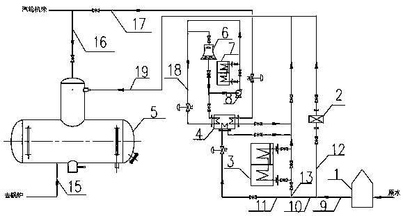
[0021] like figure 2 shown.

[0022] A recovery system for desalinated water to absorb waste heat in a thermal power plant, which includes a water treatment device 1, a desalinated water recovery slag cooler waste heat device 2, a steam seal cooler 3, a heat pump 4, a deaerator 5, a cooling tower 6, and a maintenance cooling device 7 , the desalinated water of the water treatment device 1 is divided into multiple branches, and the waste heat of the slag cooler 2, the steam seal cooler 3, and the heat pump 4 are merged into the main pipeline 19 and entered into the deaerator 5 through the desalinated water, and the specific connection structured as figure 2 as shown, figure 2 The desalinated cold water pipeline 9 after treatment by the reclaimed water treatment device 1 is divided into one road, enters the desalted water recovery slag cooler waste heat device 2 to absorb heat, and enters the main pipe 19 through the first branch road 12, and enters the other road through t...

Embodiment 2

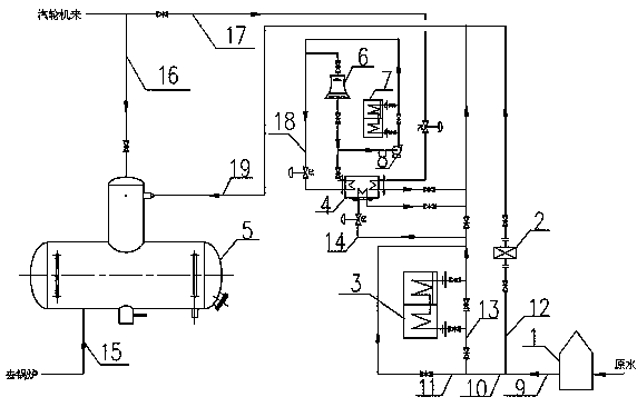
[0025] like image 3 shown.

[0026] A recovery system for desalinated water to absorb waste heat in a thermal power plant, which includes a water treatment device 1, a desalinated water recovery slag cooler waste heat device 2, a steam seal cooler 3, a heat pump 4, a deaerator 5, a cooling tower 6, and a maintenance cooling device 7 , the desalinated water of the water treatment device 1 is divided into multiple branches, and the waste heat of the slag cooler 2, the steam seal cooler 3, and the heat pump 4 are merged into the main pipeline 19 and entered into the deaerator 5 through the desalinated water, and the specific connection structured as image 3 as shown, image 3 The demineralized cold water pipeline 9 treated by the water treatment device 1 is divided into one path through the first branch 12 and enters the desalinated water recovery slag cooler waste heat device 2 to absorb heat and then enters the main pipeline 19, and the other path passes through the second ...


PUM


Abstract

A recovery system for desalinated water to absorb waste heat from a thermal power plant, which includes a water treatment device (1), a desalinated water recovery slag cooler waste heat device (2), a steam seal cooler (3), a heat pump or heat exchanger (4) and a desalination machine Oxygenator (5), cooling tower (6) and locomotive cooling device (7), characterized in that the desalinated water of the water treatment device (1) is divided into multiple branches, and the waste heat of the slag cooler (2), The steam seal cooler (3), heat pump or heat exchanger (4) is merged into the main pipeline (19) and enters the deaerator (5). The invention can effectively recover steam turbine waste heat and boiler high-temperature slag discharge heat, utilize heat pump or heat exchanger to recover the heat discharged to the atmosphere from circulating cooling water, reduce boiler desalted water heating self-use steam consumption in deaerator, save thermal power plant energy, and improve Heating capacity and economy of thermal power plants.

Description

technical field [0001] The invention relates to a waste heat recovery technology, in particular to a power plant waste heat recovery technology, in particular to a recovery system for desalinated water to absorb heat power plant waste heat. Background technique [0002] At present, for the thermal power plant with back pressure unit used for heating, the exhaust steam is directly sent to the heat user without condensed water recovery. Before entering the deaerator, the water needs to be preheated and boiled to remove oxygen. Therefore, more steam is consumed for heating when replenishing water, and the heating efficiency is reduced. In the circulating cooling water system, there is a large amount of waste heat in the steam turbine auxiliary equipment such as the slag cooler and the steam seal cooler, which needs to be taken away by the circulating cooling water and released into the atmosphere, resulting in a waste of waste heat in the auxiliary system and serious water evap...

Claims


Application Information

Patent Timeline
Patent Type & Authority Patents(China)
IPC IPC(8): F22D11/02C02F1/20F22D1/50
CPCY02B30/52
Inventor 郭宏新李奇刘丰树童张贤福
Owner JIANGSU SUNPOWER TECH
Why Eureka
Try Eureka