Method for preparing esd device, esd device

An ESD device and epitaxial layer technology, which is applied in the manufacturing of semiconductor devices, electric solid-state devices, and semiconductor/solid-state devices, etc., can solve problems such as difficulty, increasing leakage current of device leakage junction capacitance, and reducing the performance of semiconductor devices.

Active Publication Date: 2019-04-26
SEMICON MFG INT (SHANGHAI) CORP
View PDF4 Cites 0 Cited by
  • Summary
  • Abstract
  • Description
  • Claims
  • Application Information

AI Technical Summary

Problems solved by technology

[0002] With the continuous development of semiconductor technology, the size of MOSFET is being greatly reduced, but due to the limitation of gate oxide layer thickness and power supply voltage, it is difficult to effectively suppress the short-channel effect (short-channel effect, referred to as SCE) of the device.
[0003] At present, the ultra-shallow junctions (USJ) process is generally used to improve the SCE of ESD (Electro-Static discharge, electrostatic discharge) devices, but it will significantly increase the drain junction capacitance of the device. ) and leakage current (junction leakage), especially in the NMOS device (NMOS with two-step S / D implantation) prepared by the two-step S / D implantation process, due to the high supply voltage (supply voltage), the drain terminal The ion implantation region or the halo ion implantation region (such as ion implantation using a heavily-doped halo) has a high electric field at the junction (drain / halo junction), thereby reducing the semiconductor device performance
[0004] In addition, in the current HKMG process, after the lightly doped process (LDD) and the isolation process, SiGe is used for the preparation process of the high-K metal gate, but the devices prepared by the above process steps are undergoing wafer testing (WaferAcceptance Test, WAT for short), there will be serious leakage induction barrier lowering effect (Drain induction barrier lower, DIBL for short) and leakage current, and it is difficult to adjust LDD (Low doped drain) and pocket implantation (Pocket implantation, PKT for short) process Parameters such as energy, dose, ion implantation tilt angle or using double PKT process to improve the DIBL and leakage current of the above devices

Method used


Image

  • Method for preparing esd device, esd device
  • Method for preparing esd device, esd device
  • Method for preparing esd device, esd device

Examples


Embodiment 1

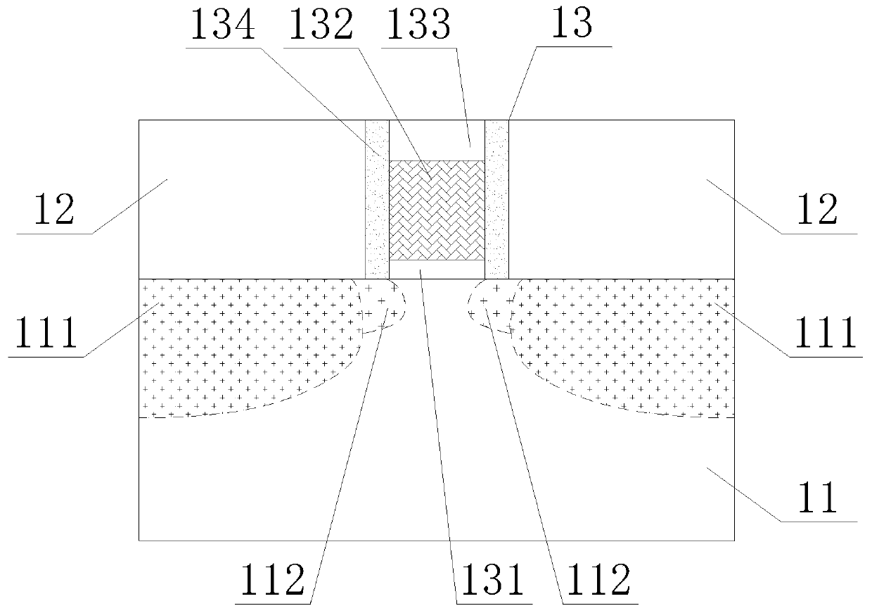
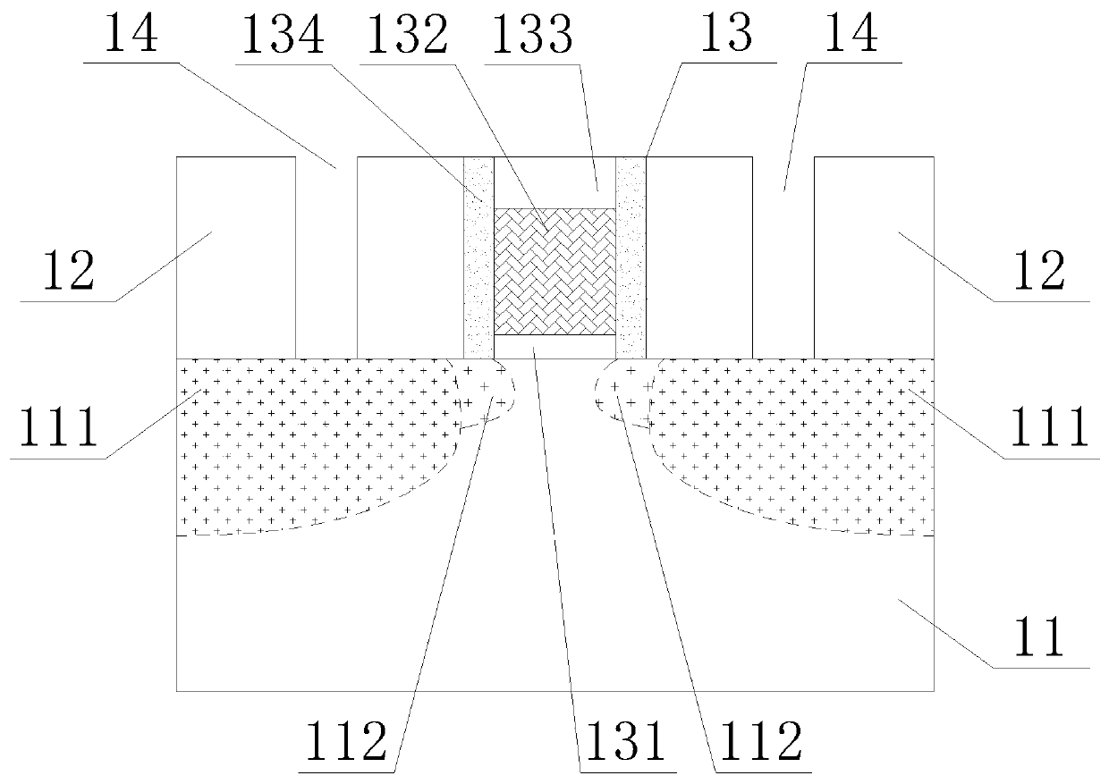
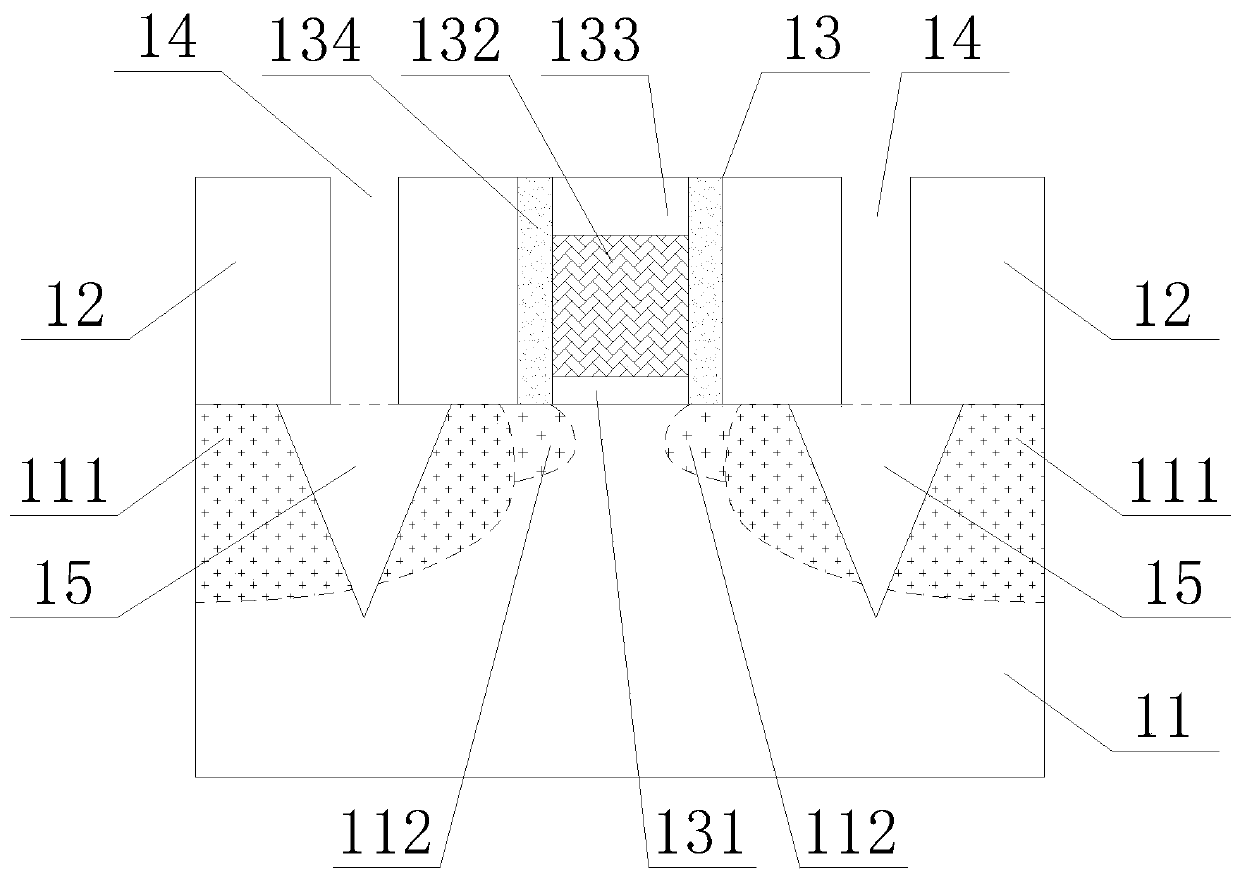
[0041] Figure 1~5 It is a schematic flow chart of the method for preparing an ESD device in Example 1 of the present application; as Figure 1~5 As shown, this embodiment is based on the preparation process of ESD devices based on the traditional preparation of MOS devices, specifically:

[0042] Such as figure 1 As shown, a silicon substrate 11 prepared with a well region is provided, and a gate stack structure 13 (gate stack after well) is prepared on the silicon substrate 11; the gate stack structure 13 can be prepared based on a traditional MOS device The high-k metal gate structure (HKMG) prepared by the process includes a gate oxide layer 131, a metal gate 132, a low resistance layer 133 and sidewalls 134, and the gate oxide layer 131 covers part of the upper surface of the silicon substrate 11, and the metal The gate 132 covers the upper surface of the gate oxide layer 131, the low-resistance layer 133 covers the upper surface of the metal gate 132, and the spacer 134...

Embodiment 2

[0051] Figure 6 It is a structural schematic diagram of an ESD device in Embodiment 2 of the present application; on the basis of the method for preparing an ESD device in Embodiment 1 above, the ESD device in this embodiment can be formed, specifically:

[0052] Such as figure 2 As shown, on the silicon substrate 21 forming the source / drain region 211, a gate stack structure 22 is provided, and the gate stack structure 22 may be a high-k metal gate structure (HKMG ), which specifically includes a gate oxide layer 221, a metal gate 222, a low-resistance layer 223, and sidewalls 224, and the gate oxide layer 221 covers part of the upper surface of the silicon substrate 21, and the metal gate 222 covers the upper surface of the gate oxide layer 221. On the surface, the low-resistance layer 223 covers the upper surface of the metal gate 222, the sidewall 224 is located on the upper surface of the silicon substrate 21 and covers the sidewalls of the gate oxide layer 221, the me...


PUM

PropertyMeasurementUnit
depthaaaaaaaaaa

Abstract

The invention relates to the technical field of semiconductor manufacturing, and specifically relates to a method of preparing an ESD (Electro-Static Discharge) device and an ESD device. The method of preparing an ESD device comprises the steps: based on a traditional method of preparing an MOS device (such as a PMOS or EMOS device), implanting ESD ions into a mask to open a dielectric layer above a source / drain area; utilizing a wet etching process to form a wide-top and narrow-bottom V type groove in a silicon substrate; and generating two epitaxial layers with different ion doping concentration in the V type groove continuously to form a triangular epitaxial stress layer (namely, a bottom epitaxial layer) in the source / drain area so as to realize the aim of enhancing the channel surface stress and optimizing the ESD trigger voltage on the premise of not performing the ESD ion implantation process and to greatly improve the performance of the ESD device while the device SEC (Short-Channel Effect) can be effectively improved.

Description

technical field [0001] The invention relates to the technical field of semiconductor manufacturing, in particular to a method for preparing an ESD device and an ESD device. Background technique [0002] With the continuous development of semiconductor technology, the size of MOSFET is being greatly reduced, but due to the limitation of gate oxide layer thickness and power supply voltage, it is difficult to effectively suppress the short-channel effect (short-channel effect, referred to as SCE) of the device. [0003] At present, the ultra-shallow junctions (USJ) process is generally used to improve the SCE of ESD (Electro-Static discharge, electrostatic discharge) devices, but it will significantly increase the drain junction capacitance of the device. ) and leakage current (junction leakage), especially in the NMOS device (NMOS with two-step S / D implantation) prepared by the two-step S / D implantation process, due to the high supply voltage (supply voltage), the drain termin...

Claims


Application Information

Patent Timeline
Patent Type & Authority Patents(China)
IPC IPC(8): H01L21/77H01L27/02H01L21/336H01L21/265
Inventor 赵猛
Owner SEMICON MFG INT (SHANGHAI) CORP
Why Eureka
Try Eureka