Photoacoustic microscope system

A photoacoustic microscope and photoacoustic signal technology, which is applied in the direction of material analysis, measuring devices, and instruments through optical means, can solve the problems of increasing the complexity and cost of the imaging system, loss of light energy by the side lobes of the beam, and prolonging the imaging time. , to achieve the effect of solving luminous flux loss, high luminous flux rate, simplified design and component cost

Inactive Publication Date: 2016-11-02
SHENZHEN INST OF ADVANCED TECH CHINESE ACAD OF SCI
View PDF2 Cites 6 Cited by
  • Summary
  • Abstract
  • Description
  • Claims
  • Application Information

AI Technical Summary

Problems solved by technology

However, the ineffective side lobes of the beam in this method will lose a lot of light energy, and multiple laser irradiations greatly prolong the imaging time, and at the same time

Method used


Image

  • Photoacoustic microscope system
  • Photoacoustic microscope system
  • Photoacoustic microscope system

Examples


Embodiment Construction

[0024] The present invention will be further described in detail below through specific embodiments in conjunction with the accompanying drawings.

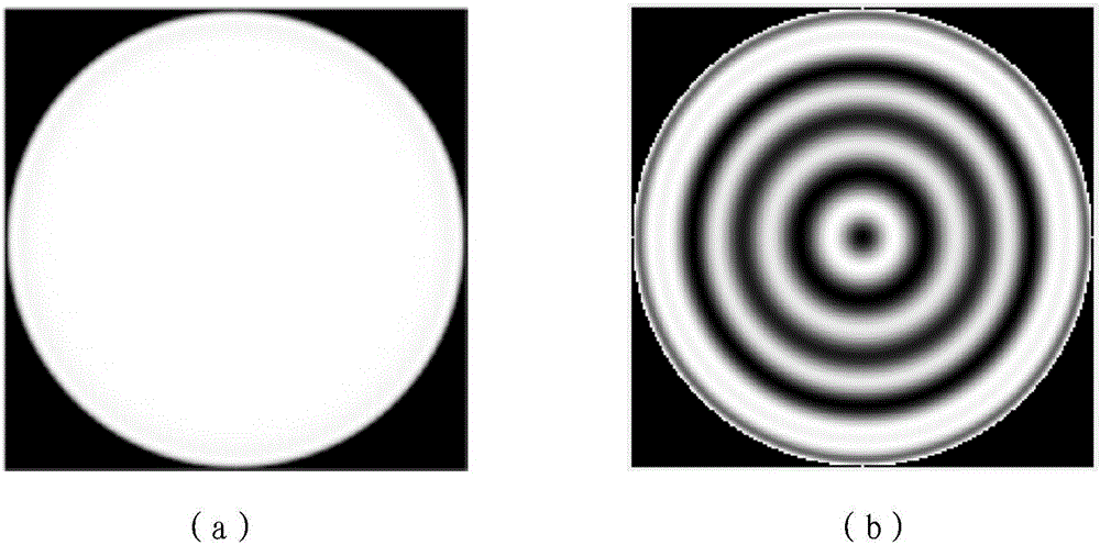
[0025] In this application, a liquid crystal spatial light modulator is used to modulate the wavefront of the incident beam, thereby significantly improving the optical resolution of the imaging focal depth of the photoacoustic microscope. The liquid crystal spatial light modulator is the core component to realize beam wavefront shaping. figure 1 The binary image shown in (b) is loaded on the liquid crystal spatial light modulator, causing changes in the optical properties of the liquid crystal molecules, and corresponding changes in the wavefront of the beam incident on the surface of the spatial light modulator. In the optical path of the system, the photoacoustic excitation beam is incident on the surface of the spatial light modulator, and loaded on the specific light mode of the spatial light modulator (such as figure 1 (b) ...


PUM


Abstract

The invention discloses a photoacoustic microscope system. Pulse laser is emitted through a laser source, the pulse laser goes through a polarizing film and then forms linearly polarized light, the linearly polarized light is subjected to collimation and beam expanding under the action of a shaping light path and then is emitted to the surface of a spatial light modulator, the modulated pulse light irradiates tissue, a photoacoustic signal reception device located at the other end of the tissue receives a photoacoustic signal and transforms the acoustic signal into an electric signal, a data acquisition and processing device acquires the electric signal and stores the data and a 3D image and a cross section image of the tissue are obtained through 3D reconstruction. The spatial light modulator is used in the light path so that optical focal depth is substantially increased and large-focal depth and high-resolution photoacoustic imaging is realized. The photoacoustic microscope system is free of an axicon for producing Bessel light beams, solves the problem of an axicon luminous flux loss, is free of two laser irradiation processes at a short time interval for Bessel light beam sidelobe influence elimination, simplifies experiment device design and part costs and prevents high energy thermal relaxation effect-caused damage to biological tissue.

Description

technical field [0001] The present application relates to the field of photoacoustic imaging, in particular to a photoacoustic microscope system. Background technique [0002] Photoacoustic imaging based on light absorption characteristics organically combines two methods of light excitation and acoustic detection. Pigment substances in biological tissues absorb pulsed laser light and convert them into thermal energy. Due to the instantaneous thermoelastic effect, broadband ultrasonic waves (ie, photoacoustic signals) are released outward, and the light absorption characteristics of tissues can be measured by detecting photoacoustic signals. The rapid development of optical resolution photoacoustic microscopy in recent years has improved the lateral resolution to the micron level, and can image the blood microcirculation system in vivo with high precision, including main vessels at all levels, capillaries, and even individual red blood cells. By analyzing the depth position...

Claims


Application Information

Patent Timeline
IPC IPC(8): G01N21/17
CPCG01N21/1702G01N2201/06113
Inventor 吴玉立宋伟高玉峰宋亮方晖
Owner SHENZHEN INST OF ADVANCED TECH CHINESE ACAD OF SCI
Why Eureka
Try Eureka